Circuit diagrams – Carbolite TZF Series User Manual
Page 14
STF/TZF
14
MF08 – 3.24
7.0 C
IRCUIT
D
IAGRAMS
EMC Filters (if fitted): dependent on the model there may be one filter, or more than one fitted in
parallel. The circuit diagram examples do not show multiple filter arrangements.
NOTE!!! for TZF models for USA the diagrams of section 7.9 may apply.
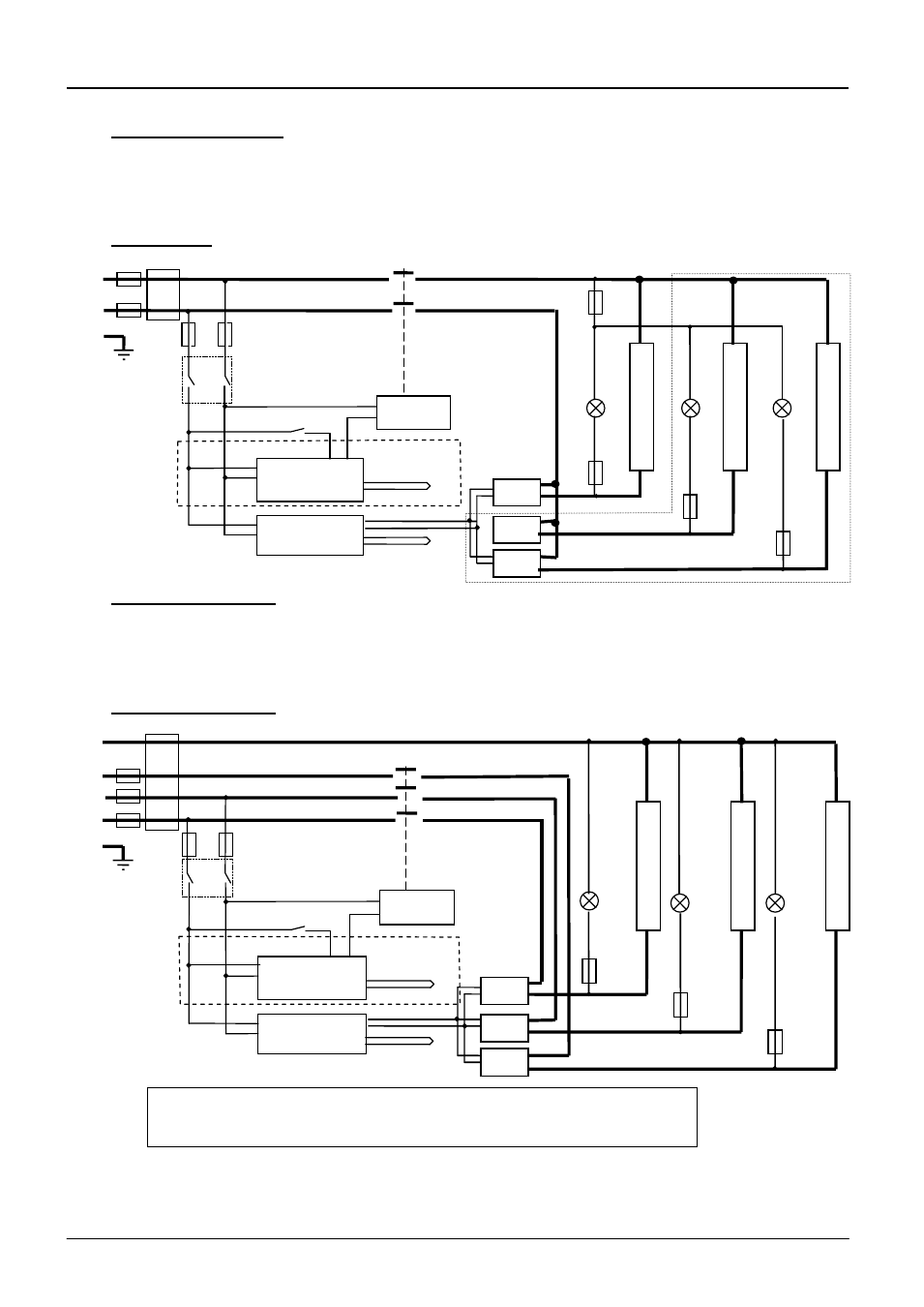
7.1 Single Phase
7.2 2-phase with neutral
As the following 3-phase diagram, except that one phase is not present.
Note that if the phase current is less than 25A/phase, a direct safety switches may be fitted in the
element circuit, rather than the switch shown in the coil circuit.
7.3 3-phase with neutral
e
l
e
m
e
n
t
(s)
e
l
e
m
e
n
t
(s)
F3
F1
N
F2
L
PE
e
l
e
m
e
n
t
(s)
Instrument Switch
coil
temperature
controller
thermocouple
overtemp.
controller
thermocouple
SSR
heat
on
F3
SSR
SSR
heat
on
F3
heat
on
F3
Filter (if fitted)
if over-
temperature
fitted
Contactor
if fitted: 2- or 3- circuit
models
Heater Switch
e
l
e
m
e
n
t
(s)
e
l
e
m
e
n
t
(s)
F1
N
L2
L3
F2
L1
PE
e
l
e
m
e
n
t
(s)
Instrument Switch
coil
temperature
controller
thermocouple
overtemp.
controller
thermocouple
SSR
heat
on
F3
SSR
SSR
heat
on
F3
heat
on
F3
Filter (if fitted)
Contactor
note on (2- and) 3-phase: depending on filter(s) fitted, there may be (2
or) 3 separate neutral wires from the elements to the neutral supply.
if over-
temperature
fitted
Heater Switch