Auto Meter 2895 User Manual
Calibration, Mounting light replacement, Tachometer
2650-1139
QUESTIONS:
If after completely reading these instructions you have questions regarding the operation or installation of your instrument(s),
please contact Auto Meter Technical Service at
815-899-0801.
You may also email us at
Additional information can also be found at
http://www.autometer.com/tech_faq.aspx
Calibration
IMPORTANT: This tachometer is factory calibrated to
operate on 8 cylinder engines. For 4 or
6 cylinder engines, it is necessary to
make the proper adjustments to adapt
this tachometer to your cylinder range.
NOTE: Calibration changes do not apply to the Jr. Dragster
tachometer. The Jr. Dragster tachometer is calibrated
to operate only on Briggs & Stratton engines.
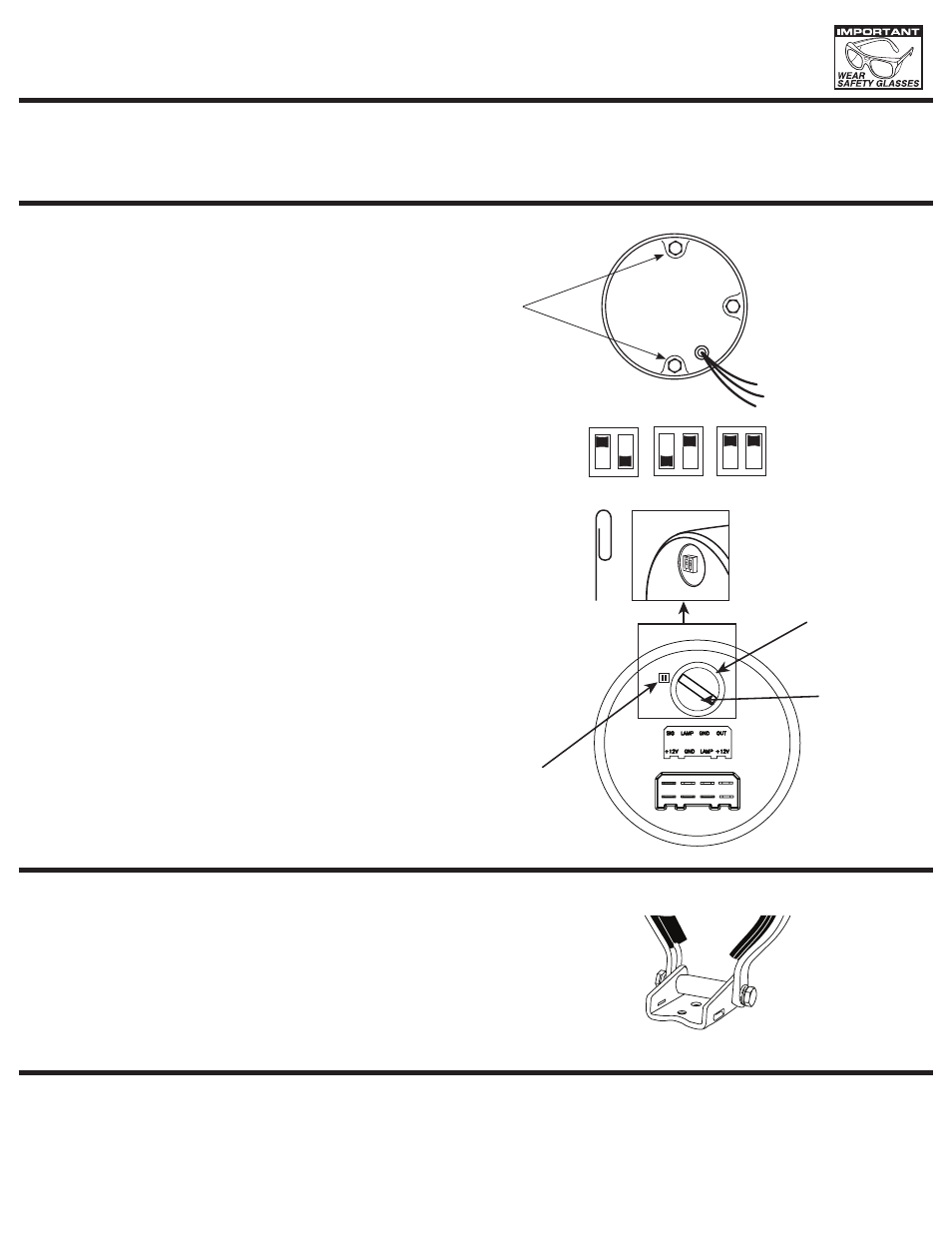
Figure B.
4 CYL. - Switch One up, Switch Two down
6 CYL. - Switch One down, Switch Two up
8 CYL. - Both switches up
If you are unsure of your vehicle’s pulse(s) per revolution
or specific calibration requirements, contact Auto Meter
Technical Service Dept. at (815) 899-0801, or go to
www.autometer.com/hp/tectips for information.
Switch is not visible
from from this angle,
shown for location only.
Access switch
through
light hole.
(Angle view through access hole)
Figure B
1
1
2
2
1
2
4 CYL. / 2 PULSE
6 CYL. / 3 PULSE
8 CYL. / 4 PULSE
UP DN
DN UP
UP UP
To change the tachometer calibration, access to the inner case
is necessary. Remove the two acorn nuts as shown in figure A
and carefully slide the cup of the tachometer back in order to
access the inner case. Locate the switch access hole on the inner
case. Remove twist-lock light socket to access the calibration
switches. (See light replacement) Use a small screwdriver or an
unwound paper clip to change the switch settings. Move each of
the two switches to the proper cylinder selection according to the
diagram illustrated on the right.
NOTE: This tachometer has an air core meter. With power off,
It is normal for the pointer to leave zero. When power
is applied, the pointer will move to the correct position.
Figure A
Acorn
Nuts
Twist In
light
Figure C
Mounting
Light Replacement
3
3
/
8
" SIZE
SHOWN
The special design of the tachometer base allows for a variety of mounting possibilities.
Loosening the hex screws at the mounting base allows the tachometer to be rotated in
the strap. Also, this design allows the tachometer face to be angled forward or backward
for better viewing. Attach the base using screws provided or some other fasteners.
See figure C. Rotate twist-lock socket counterclockwise using needle nose pliers and remove.
Replace old bulb with GE 194 bulb.
INSTALLATION INSTRUCTIONS
TAChOMETER