Auto Meter 8592 User Manual
Diesel exhaust pressure gauges, Installation, Exhaust particle trap recommendation wiring
INSTALLATION INSTRUCTIONS
DIESEL EXHAUST PRESSURE GAUGES
2650-1700-00
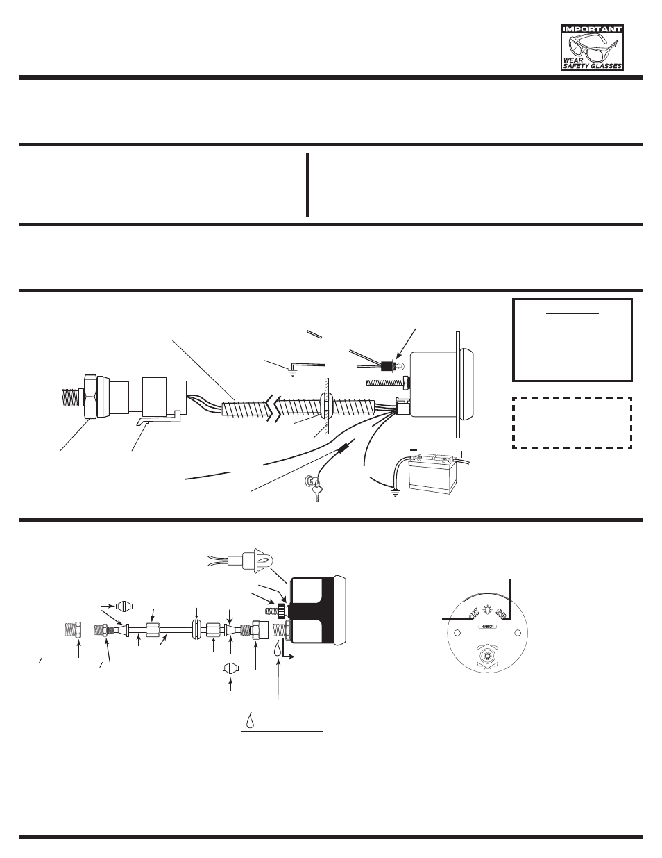
CAUTION!
As a safety precaution, the
+12V terminal of this product
should be fused before
connecting to the 12V ignition
switch. We recommend using a
3 Amp, automotive type fuse.
NOTE: When the ignition
is off the pointer
may not always
rest at zero.
QUESTIONS
:
If after completely reading these instructions you have questions regarding the operation or installation of your instrument(s),
please contact Auto Meter Technical Service at
866-248-6357.
You may also email us at
Additional information can also be found at
http://www.autometer.com
Installation
1. The 2
1
⁄
16
" gauges may be mounted in a 2
1
⁄
16
" diameter hole. The
hole may be either a hole in the dash, a gauge panel or an Auto
Meter Gauge Pod. (It is best to connect all wiring to the gauge
before mounting it into the gauge hole.)
2. Follow the diagram below to connect 12 volt lighting.
The pointer will move backward to the stop pin and then move to
the zero box. This procedure is an auto-calibration function and is
performed on every power-up. While this test is being performed,
the gauge may make a clicking sound. This is normal.
Exhaust Particle Trap Recommendation
Wiring
To extend the maintenance period on the copper coil, Auto Meter recommends the installation of the Diesel Particle Trap kit, model #5375. The Diesel Particle
is inserted between the copper tubing and either the FSE pressure sensor or the nylon tubing used on the mechanical gauge. The trap provides an expansion
chamber for the soot particles to collect, similar to a dust collector. It also incorporates a z brass snubber to minimized pressure spikes at the pressure sensor or
mechanical gauge. It is easy to open for removing accumulated soot.
SENDER
12V BATTERY
GOOD ENGINE GROUND
GROMMET
+12v CONNECTION
RED
BLACK
+12v DASH
LIGHTING
GOOD
ENGINE
GROUND
WHITE
BLACK
WIRING
HARNESS
FUSE
(SEE CAUTION LEFT)
FIREWALL
OPTIONAL
SLIT TUBING
RECOMMENDED
(AVAILABLE AT MOST
HARDWARE STORES)
(for standard incandescent
lit instrument)
FOR INTERNAL LED
LIT INSTRUMENTS
WHITE
+12v DASH
LIGHTING
Power-Up
ADAPTER
PORT NUT
USE TEFLON
SEALING COMPOUND
ON PIPE THREADS
4" NPT ADAPTER
8" NPT ADAPTER
SMALL
GROMMET
NYLON TUBING
1
1
FERRULE
FERRULE
LOCK WASHER
THUMB NUT
OR
OR
FERRULE
COMPRESSION
NUT
COMPRESSION
NUT
CONNECT TO
12V LIGHTING
CONNECT TO
GOOD GROUND
Mounting and Connecting Mechanical Gauges
GROUND
INTERNAL LED
LIGHTED MODELS
+12 VOLT
LIGHTING
NOTE: DO NOT OVER TIGHTEN
ADAPTER FITTING OR
GAUGE MAY BE DAMAGED.
NOTE: DO NOT
LOOSEN PORT NUT
OR GAUGE MAY
BE DAMAGED.
MOUNTING
BRACKET
1. Gauges may be mounted in In-dash holes, or in Auto Meter custom mounting
Solutions. Secure gauge with mounting clamps supplied. 2-
1
⁄
16
" gauges mount
in 2-
1
⁄
16
" diameter hole.
2. Drill
3
⁄
8
" dia. holes and install rubber grommet where pressure line passes
through sheet metal, such as firewall.
3. Attach nylon pressure line to fitting on back of gauge using adapter, ferrule,
and compression nut as shown in diagram above. Route line through grommet
Connect the nylon line to the coiled copper tube attached to the exhaust
manifold using 1/8" connector.
4. Make sure line is free from hazard of moving parts or hot engine components.
It is recommended that Auto Meter 3224 copper tubing kit be used where a
potential hazard exits.
5. Start engine and thoroughly check installation for leaks.
6. Twist in light socket assembly and connect one wire to dash lighting circuit or
other 12V power source and the other wire to a good ground.