Auto Meter 5646 User Manual
Elite series full sweep electric pyrometer, Important, Probe installation installation
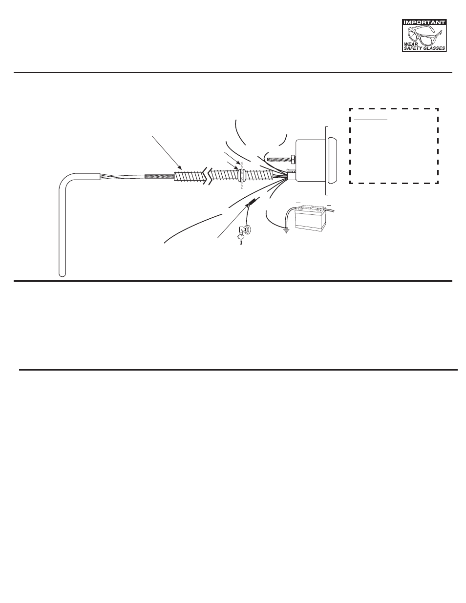
12V BATTERY
Grommet
Firewall
OPTIONAL SLIT TUBING RECOMMENDED
(AVAILABLE AT MOST HARDWARE STORES)
Pro Control
Low Output #1
Pro Control
High Output #2
Red
Blue
Or
ange
Blac
k
Blac
k
+12v Dash
Lighting
Fuse
(See Caution Left)
+12v Connection
Important: See "Lighting Mode"
Good Engine Ground
Pro Control
Ground
INSTALLATION INSTRUCTIONS
ELITE SERIES
fULL SwEEp ELECTRIC pyROmETER
2650-1459-00
CAUTION:
As a safety precaution, the
+12V terminal of this product
should be fused before
connecting to the 12V ignition
switch. We recommend using
a 1 Amp, 3AG fast-acting type
cartridge fuse (Littlefuse
®
#
312 001 or an equivalent).
NOTE: When the ignition is off the pointer may not always rest at zero.
Important
Pyrometers are sensitive, high accuracy instruments. They must be handled and installed with care to insure proper performance. Carefully read and
follow these instructions, and your pyrometer will provide you with a long and accurate life.
pROBE INSTALLATION
INSTALLATION
1. Check that you have all parts required for installation, and the engine is cool.
2. Disconnect the negative (-) battery cable.
3. Gauge mounts in a 2
1
/
16
” hole. Use supplied brackets and nuts to secure gauge to dash.
4. Drill 1” diameter hole where wires pass through sheet metal (such as firewall) and install rubber grommet provided.
(Grommet will require slit.)
5. Connect the white wire to dash lighting or switchable 12v light source, red wire from harness to +12V terminal on
ignition switch or other +12V power source, and black wire to ground.
6. Reconnect negative (-) battery cable.
1. Begin by installing the thermocouple in the exhaust, then work back to the gauge. Installing the probe in the proper location will
insure optimal temperature readings. For non-turbo engines, install the probe 1-2 inches from the cylinder head.
For turbo engines, remove the exhaust manifold and install the probe 1-2 inches from the cylinder head. If the exhaust manifold
can not be removed, install the probe 1-2 inches after the turbo exhaust outlet (Exhaust gas temps could drop over 200˚ when
installing after the turbo). CLEAN ALL METAL FILINGS out of the exhaust manifold. Metal filings will damage the turbo impellor
if they go through the turbo.
The probe can be mounted in two different ways, so please use the method best suited for your needs.
A) Pre-existing
1
/
8
” NPT Threaded Hole: Simply screw the threaded fitting into the hole, insert the probe, and tighten the set
screw snugly onto the probe. (Caution: do not over tighten set screw or damage to probe may occur.) Make sure the probe is
oriented so the wires do not come in contact with, or become too close to the manifold or other hot engine parts.
See illustration for details.
B) Stainless Clamp Method: This method is for applications that require frequent removal of the manifold or header for service,
or just faster and easier installation. Drill a
7
/
16
” diameter hole about 6” down from the junction of the exhaust pipe to manifold
junction. Undo the clamp and slide the probe into the hole in the clamp. Slide the set screw collar onto the probe.
Before tightening the collar in position make sure that when inserted, the probe will have its tip in the middle two-thirds of the
exhaust stream. Tighten screw collar in position. (Caution: do not over tighten set screw or damage to probe may occur.)
Hold the clamp open when inserting the probe into the
13
/
32
” hole. Re-join the clamp ends and tighten in position.
Make sure the probe is oriented so the wires do not come in contact with, or become too close to the manifold or other hot
engine parts. See the illustration below for details.
2. With the probe installed, the wire harness can now be routed to the gauge. The wire harness is an integral part of the pyrometer
calibration. It may not be shortened or lengthened without affecting the gauge calibration. You will need to determine a suitable
location to coil the excess wire, and tie it loosely with a wire tie. (Loosely tying the excess coil prevents embritlement caused by
vibration.) Pass the harness through the fire wall using an existing hole, or drill a 1” diameter hole and use the rubber grommet
provided to protect the wire from damage.
White