Appendix #2 20’ navi-trac lt clearspan, Assembly of 20’ navi-trac clearspan (cs) units – Anchor NAVI-TRAC LITE 20 WIDE User Manual
Page 19
10’
10’
53
54
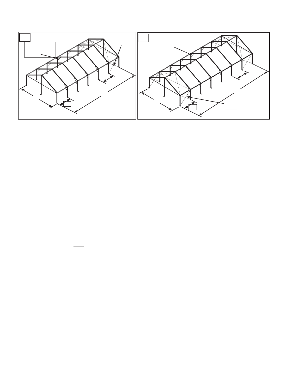
X-CABLED BAY FOR
EACH ADDITIONAL
60 FT OF LENGTH
X-CABLED
BAY
KNEE BRACES
ON INNER
BEAMS
KNEE BRACES
ON INNER
BEAMS
70’
10’
(MAX)
20’
60’
20’
Appendix #2
20’ Navi-Trac LT Clearspan
19
CLEARSPAN UNITS UP TO 60 FT IN LENGTH
CLEARSPAN UNITS EXCEEDING 60 FT IN LENGTH
10’
(MAX)
ASSEMBLY OF 20’ NAVI-TRAC CLEARSPAN (CS) UNITS
NAVI-TRAC LT Clearspan (CS) units are installed with the same procedure as the Gabled-Gabled End or Hip styles pre-
viously described, except that the baseplates are hinged, allowing the beams to be pivoted to vertical. For this reason,
the Clearspan footprint can be laid out ahead of time, with baseplates positioned and anchored to the ground. The 20’
Clearspan units differ from the LT (Lite) unit in the following important ways:
1. The 20’ Clearspan units have no external guy webs.
2. All inner beams are Knee Braced on both sides of the unit (see fig. 53).
3. The baseplates of all uprights (legs) are hinged (see parts # BH & BHG on page 4), so that the beam
can be pivoted to vertical after the baseplate has been secured to the ground or to appropriate footings.
Additionally, the base plate has (4) holes for staking or anchoring.
The Gabled End technique of standing the second beam of the unit first and stabilizing it with safety guys should
still be used in installing the Clearspan units in order to provide a safe procedure in the initial stages of assembly
before the first bay is stabilized.
NOTE: (2) 1” x 30” steel stakes are provided for each baseplate. The actual loading may require additional stakes
or other anchoring methods to properly meet the loads defined on the blue print or the summary of engineering
analysis. It is the customer’s responsibility to insure that proper anchoring is used to meet the required loads.