Gabled end frames – Anchor NAVI-TRAC LITE 20 WIDE User Manual
Page 16
APPENDIX #1
(GABLED-HIP) AND (GABLED-GABLED) END UNITS
GABLED-HIP END FRAME
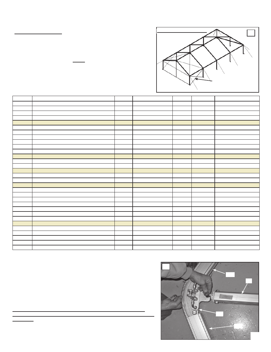
In the Hip-Gable construction, you should build the hip end first to
provide stability to the structure. Then, using the same techniques as
shown earlier, continue standing middle beams as desired.
At the final end beam, be sure to attach the Gabled End Rafter Fittings
and the End Uprights themselves before standing the beam (see fig. 44)
Notice that all Gabled ends require the X-cabling of the end bay (see fig.
43). Also, when the structure exceeds 60 ft of length, and additional X-
Cabled bay is required (see fig. 54). Parts for the Gabled End construc-
tion are listed below. For assembly procedure, see the top of page 21.
GABLED-HIP END UNITS
43
X-Cabling stabilizes
the Gabled End Bay
PARTS FOR 20’ HIP-GABLED
PER
PER
LABEL
OR GABLED-GABLED UNITS
20’
10’
(LETTER
(GABLED COMPONENTS IN ITALICS)
POSITION
ID
PART
GBL END
EXTENSION MID
ON DWG)
COMPONENT DESCRIPTION
CODE
CODE
#
KIT (#1351)
KIT (#1350)
TOP EXTRUSIONS WITH CHANNELS:
E-10
EAVE - 10’
8004400
0
2
RG-10
RIDGE W/ HOOKS - 10’
8004405
0
1
R-20
RAFTER 20’
8004425
0
2
GWE
GABLED END WING EAVE - 10’
8004460
2
0
GU
GABLED END UPRIGHT W/ TOP FITTING
8004465
1
0
PURLINS AND BRACES:
K8
KNEE BRACE (FOR CLEARSPANS ONLY)
3580650
0
[2]
UPRIGHTS:
U-8
UPRIGHT - 8’
8004450
0
2
WELDMENTS, FITTINGS & PLATES:
BA
BASEPLATES, ADJUSTABLE, 2-HOLED
8004505
0
2
BAG
BASE PLATE, GABLED END, ADJ, 2-HOLED
8004510
1
0
RW
RIDGE WELDMENTS ASSEMBLY
8004545
0
1
EW
EAVE WELDMENT W/ PINS
8004530
0
2
GWL
GABLED END WELDMENT (L)
8004535
1
0
GWR
GABLED END WELDMENT (R)
8004540
1
0
CABLES
X8-10
X-CABLE, 8’ UPRIGHT 10’ BAY
GREEN
NAVLTCS-BAY10-U8
8004550
4
0 (unless over 60’ L)
X9-10
X-CABLE, 9’ UPRIGHT 10’ BAY (FOR CS ONLY)
GREEN
NAVLTCS-BAY10-U9
8004585
[4]
0
X10-10
X-CABLE, 10’ UPRIGHT 10’ BAY (FOR CS ONLY) GREEN
NAVLTCS-BAY 10-U10 8004495
[4]
0
XR-10
X-CABLE, RAFTER, 10’ BAY
BLUE
NAVLT-BAY10
8004565
4
0 (unless over 60’ L)
NOTE: See pages 7 through 12 for staking and guying requirements.
Gabled End Frames
If you plan to use the gabled end frame on either end of the unit, it will be easier
to install the Gabled End Upright (GU) while that end beam is still on the ground.
To install, pin the Gabled End Top Fitting to the Tab at the bottom of the Ridge
Weldment. Note: if desired the hardware brackets on the outside of the Ridge
Weldment can be removed to give a cleaner outer appearance.
Caution: If you will be using Gabled Ends on both ends of your unit,
please refer to the section on Frame safety for Gabled Ends at the bottom
of page 17.
44
GU
RW
R-20
R-20
16