Completing and staking the hip end frame, Fabric guide bracket – Anchor NAVI-TRAC LITE 20 WIDE User Manual
Page 11
NOTE: SEE APPENDIX 1,
FIG. 51 & 52 FOR X-CABLING
REQUIREMENTS IN UNITS
EXCEEDING 60’ IN OVERALL
LENGTH
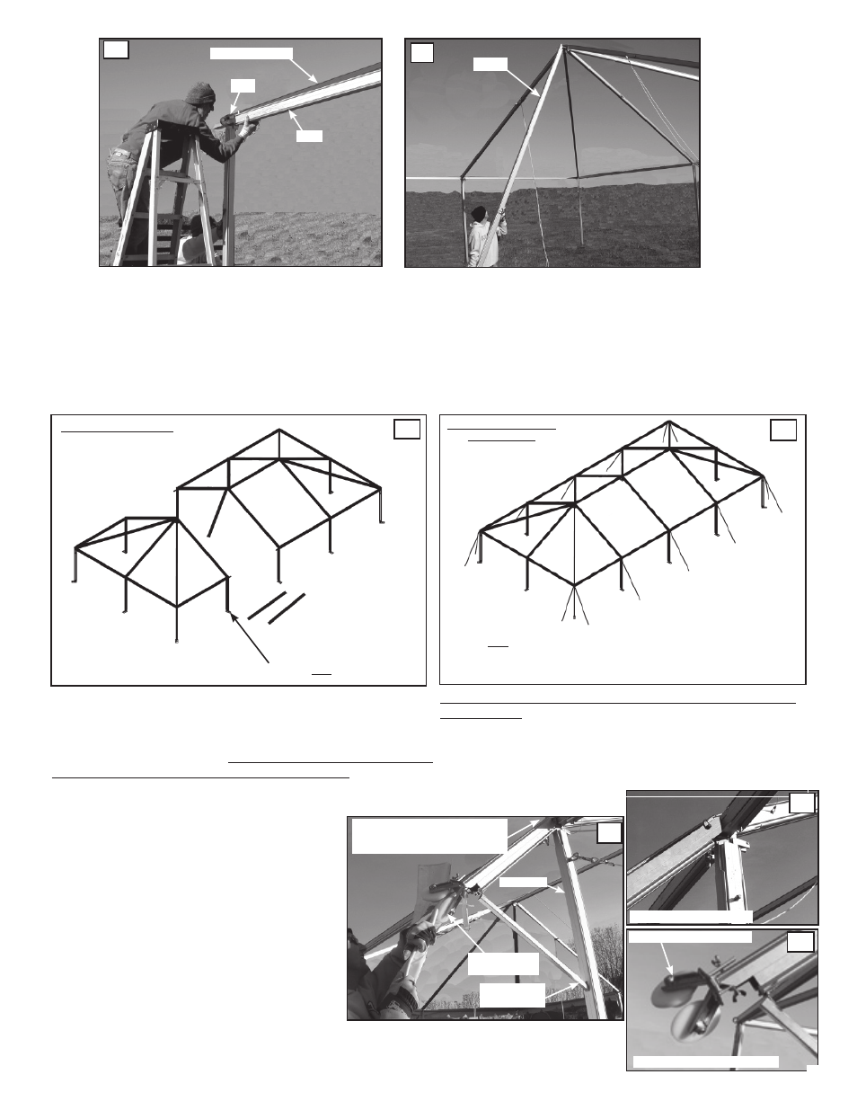
To finish out the unit, position a second, facing, hip end spaced 10’
from the last parallel middle beam and connect the purlins, ridge,
and eave bars just as in the preceding bay. Consult the blue print
for loading data for each baseplate location. Stakes alone may not
meet the loading requirement. It is the customer’s responsibility
to provide adequate anchoring to meet the loads.
Secure the new middle beam by attaching the Eave
Bars (E-10) from the standing beam to the mid beam’s
Eave Weldment as shown above.
Repeat this process with the Ridge w/Hooks (RG-10) as
shown above. Again, use the long Eave Bar Cradle to
attach the opposite end.
COMPLETING AND STAKING THE HIP END FRAME
The final middle bay joins with the cross beam of the opposite hip end (see fig. 28 & 29). Position the second (fac-
ing) hip end 10’ from the last middle beam, and use Eave Bars (E-10), and Ridge Bars w/ Hooks (RH-10) to con-
nect it to the standing frame structure.
E-10
MIDDLE BEAM
EW
RG-15
THE LAST MIDDLE BAY
HIP END UNIT WITH (2)
MIDDLE BAYS
FABRIC GUIDE BRACKET
Fabric is installed using the fabric wheeled guide
brackets and pull ropes thrown over the purlins
and eave bars from one side of the tent to the
other (see fig. 30).
To install the hinged Wheeled Guide Bracket,
slide the top over the external eye of the eave
weldment and pin in place using a Tension Lock
Pin. Spread the hinged bottom brace until the
lower end lodges in the tensioning slot of the
upright leg, as shown to the right (see fig. 31).
Using the butterfly set screws attach the Navi-Trac
Wheeled Panel Guide wheels into the open end
of the bracket at the hinged angle, as shown (see
fig. 32).
BOTTOM OF GUIDE BRACKET
TOP OF GUIDE BRACKET
Before installing fabric, all middle beams should be guyed
off, as shown. All guys are staked out from the upright at a dis-
tance equal to the height of the upright. If the breeze is strong,
the corner uprights should be guyed off as well. Later, the cor-
ner guys will be temporarily released while the fabric hip end is
being tensioned.
TENSIONING
SLOT
TOP OF BRACKET PINNED TO
THE OUTER EYE OF THE EAVE
WELDMENT
WHEELED
PANEL GUIDE
Fabric Kedar being fed between the angled
wheels of the panel guide.
WHEELED PANEL GUIDE
26
27
28
29
30
31
32
UPRIGHT
STAKE ALL BASE PLATES
STAKE ALL GUY CABLES
ACCORDING TO LOADS
SHOWN ON THE BLUEPRINT.
11