50’ navi-trac frame terminology introduction, 3square tent top frame – Anchor NAVI-TRAC 50 WIDE HIP-END User Manual
Page 3
50’ Navi-Trac Frame Terminology
INTRODUCTION:
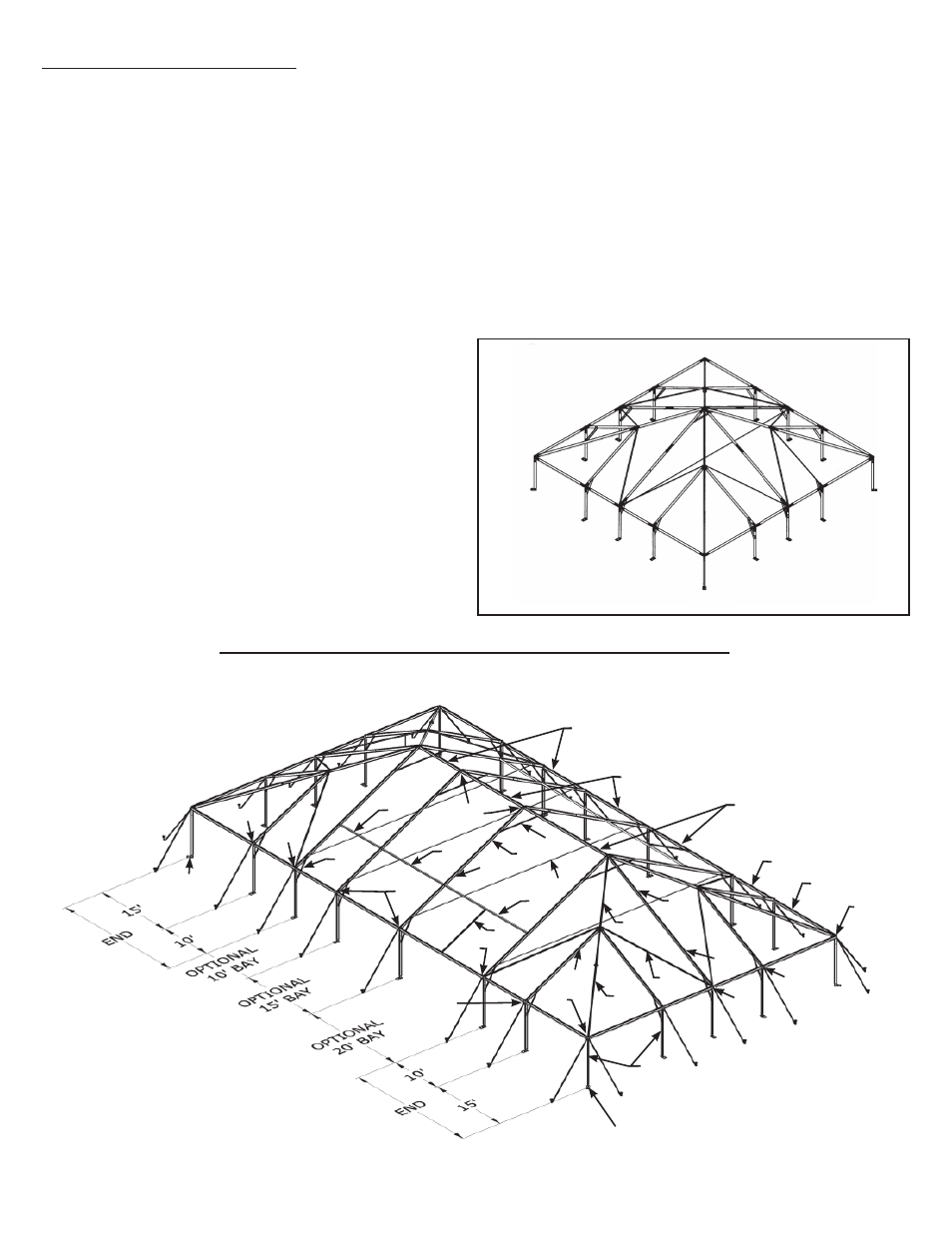
The NAVI-TRAC frame configuration is based on the hip roofed square tent shown below, right.
Hip bars connect corners to the peak, and rafters connect eave bars to the peak. The square can be
extended into a rectangle by adding 10’, 15’ or 20’ bays made up of rafters and the appropriate ridge/
eave bars (see below). In the square tent, female eave bars and rafters are connected to eave weld-
ments by rigid slip joints. Hip bars and eave/ridge bars and rafters in the middle bays use easy to
install drop-in fittings.
The NAVI-TRAC frame is made up of extruded aluminum members joined by weldments such as cor-
ner weldments, ridge weldments, eave weldments, etc. The aluminum frame members themselves are
extruded with channels into which the NAVI-TRAC fabric “kedar” is fed.
The first bay added to the square tent shape is a “starter” bay. This starter bay allows a slip fit
connection to the square tent eaves on one end of the weldment and a drop-in connection for the new
starter bay eaves on the other end of the weldment.
Subsequent bays added to the unit are “extension”
bays. Extension bays allow drop-in connections on
both ends of the eave weldments.
The chart on page 5 lists components needed for
the 50’ x 50’ square tent, the first (starter) exten-
sion, and for each additional extension to be added
to the unit. Note: starter mids or bays and exten-
sion mids are available in options of 10’, 15’ or 20’
increments of length, as shown.
BFW
BFW
U8
EIW
MCW
MRW
MLW
B4
P2
P1
P1
B3
RW
CW
H21-4
H15
R16-2
CW
E15
E10
ER20
ER15
ER10
P3
R21-9
R5-7
R21-9
R5-7
EIW
EIW
B2
C50
EIW
3
SQUARE TENT
TOP FRAME