7 interface overview, 1 power supply 24 vdc / backup – ADS-TEC IF1000 User Manual
Page 34
IF1000 series
33
© ads‐tec GmbH • Raiffeisenstr.14 • 70771 Leinfelden‐Echterdingen
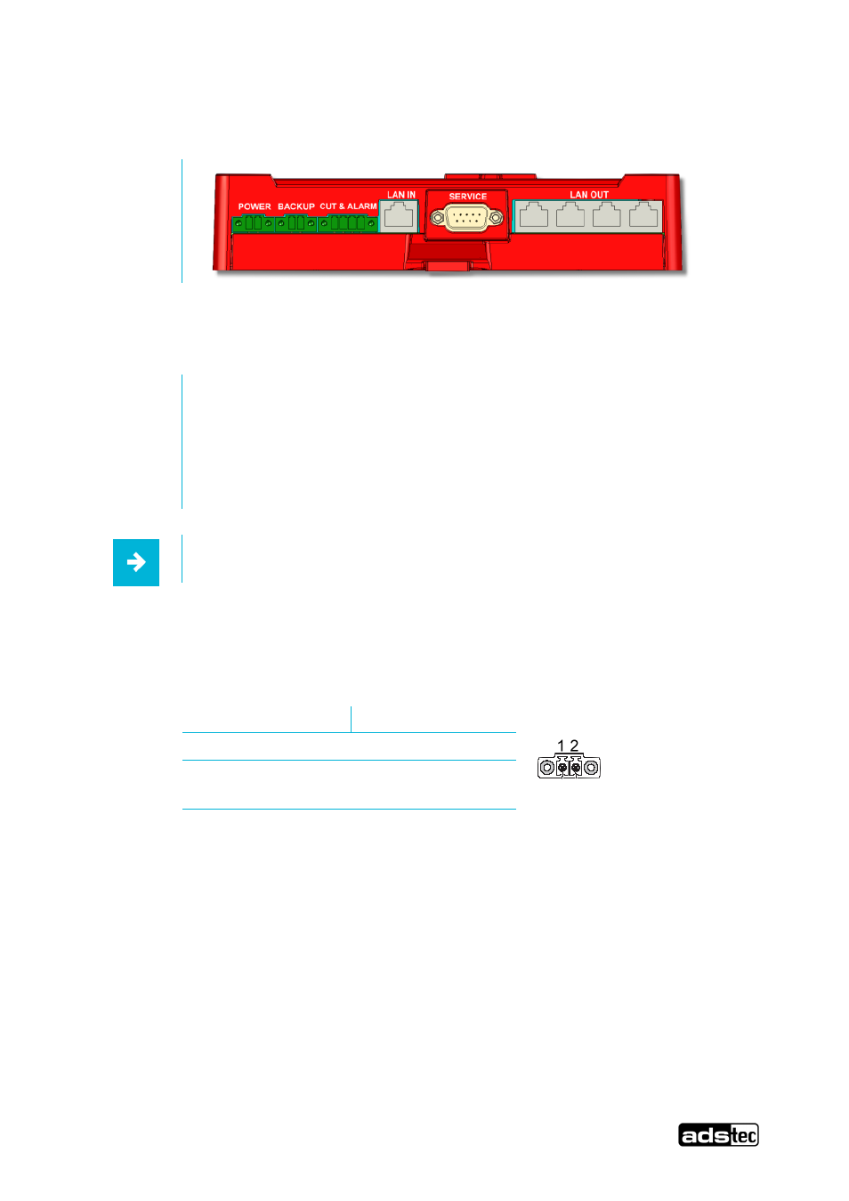
5.7 Interface Overview
Abb. 7:
The device has the following interfaces (front):
1. Power
24V DC voltage supply (2 pole COMBICON plug)
2. Backup
24V DC BACKUP voltage supply (2 pole COMBICON plug)
3. CUT& ALARM plug (4 pole COMBICON plug)
4. LAN‐in with RJ45 (PoE) or LWL fibre optic connection
5. 9 pole SUB‐D connector / RS232
6. LAN‐out with 4x RJ45 connection
Note:
All input voltages can be hooked up redundantly (Power, Backup and PoE via LAN‐in).
5.7.1 Power Supply 24 VDC / BackUp
The supply voltage implements a lead‐through terminal with screw connection (the illustration shows the jack
provided in the device))
Pin‐Number
Signal‐Name
1
24V DC
2
0 V DC
PIN 1: = L+
24V DC Power Supply
PIN 2: = GND
Ground