Connector assembly figure 2 -8, Connector assembly figure 3 -8, Connector assembly figure 4 -8 – JLG 660SJ ANSI Service Manual User Manual
Page 44
SECTION 2 - GENERAL
2-8
– JLG Lift –
3120718
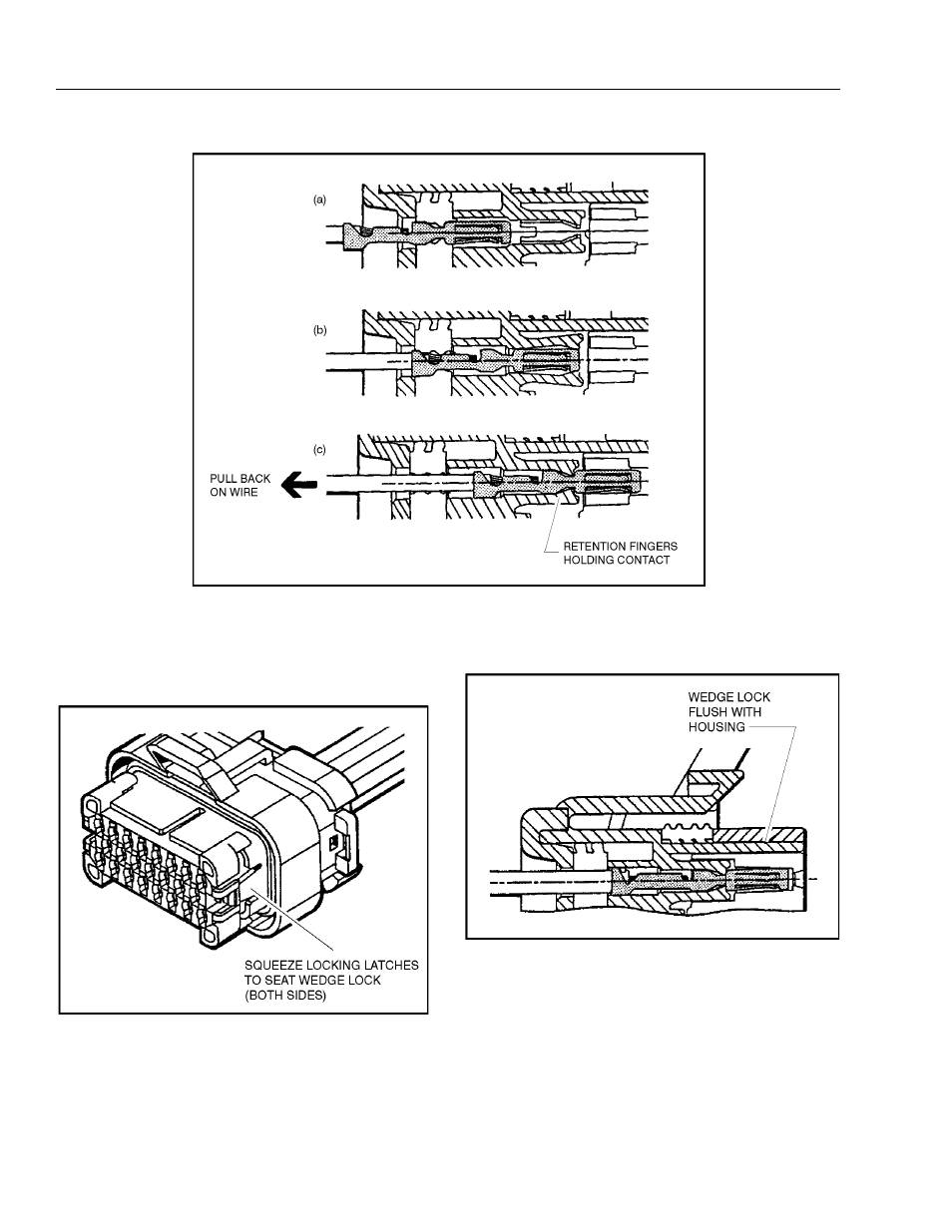
3.
After all required contacts have been inserted, the
wedge lock must be closed to its locked position.
Release the locking latches by squeezing them
inward (See Figure 2-4.).
4.
Slide the wedge lock into the housing until it is flush
with the housing (See Figure 2-5.).
Figure 2-3. Connector Assembly Figure 2
Figure 2-4. Connector Assembly Figure 3
Figure 2-5. Connector Assembly Figure 4
This manual is related to the following products: