Advance adapters inc, Np231 short shaft "fixed yoke" kit, New shaft – Advance Adapters 50-7906B User Manual
Page 8: Assembly considerations
ADVANCE ADAPTERS INC.
P/N: 50-7905, 50-7906 & 50-7906B
P.O. Box 247, 4320 Aerotech Center Way
New Item: (12/98)
Paso Robles, CA 93447
PAGE 8 OF 12
Telephone: (800) 350-2223
Fax: (805) 238-4201
Page Rev. Date:
07-31-07
SPECIAL NOTE:
The components packaged in this kit have been assembled and machined for specific type of conversions. Modifications to any of the
components will void any possible warranty or return privileges. If you do not fully understand modifications or changes that will be required to complete your conversion,
we strongly recommend that you contact our sales department for more information. This instruction sheet is only to be used for the assembly of Advance Adapter
components. We recommend that a service manual pertaining to your vehicle be obtained for specific torque values, wiring diagrams and other related equipment.
These manuals are normally available at automotive dealerships and parts stores.
NP231 SHORT SHAFT "FIXED YOKE" KIT
New Shaft
ASSEMBLY CONSIDERATIONS
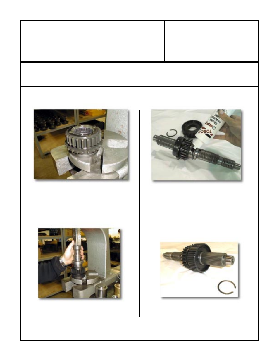
(Fig. 1A) Drive Sprocket Needle Bearings
(1) These bearings must be removed. Once the bearings are
removed, clean the inside of the drive gear to make sure it is free
of any type of debris.
On 1997 and newer transfer cases, the drive sprocket
does not use caged needle bearings. If you have this
newer style, then continue on to Fig. 3A (2).
(Fig. 2A) Pull the Needle Bearings Out
(Fig. 3A) New Main Output Shaft Assembly
(2)
Main shaft assembly:
(a) Clean all components.
(b) Prelube all components with a quality assembly lubricant.
(Fig. 3A)
(c) Slide drive sprocket into position.
(d) Slide mode hub into position.
(e) Install the retaining ring into position after the mode hub.
(Fig. 4A)
(Fig. 4A) (Large) Retaining Ring Installation
CONTINUE TO PAGE 9