Advance adapters inc, Np231 short shaft "fixed yoke" kit – Advance Adapters 50-7906B User Manual
Page 6
ADVANCE ADAPTERS INC.
P/N: 50-7905, 50-7906 & 50-7906B
P.O. Box 247, 4320 Aerotech Center Way
New Item: (12/98)
Paso Robles, CA 93447
PAGE 6 OF 12
Telephone: (800) 350-2223
Fax: (805) 238-4201
Page Rev. Date:
07-31-07
SPECIAL NOTE:
The components packaged in this kit have been assembled and machined for specific type of conversions. Modifications to any of the
components will void any possible warranty or return privileges. If you do not fully understand modifications or changes that will be required to complete your conversion,
we strongly recommend that you contact our sales department for more information. This instruction sheet is only to be used for the assembly of Advance Adapter
components. We recommend that a service manual pertaining to your vehicle be obtained for specific torque values, wiring diagrams and other related equipment.
These manuals are normally available at automotive dealerships and parts stores.
NP231 SHORT SHAFT "FIXED YOKE" KIT
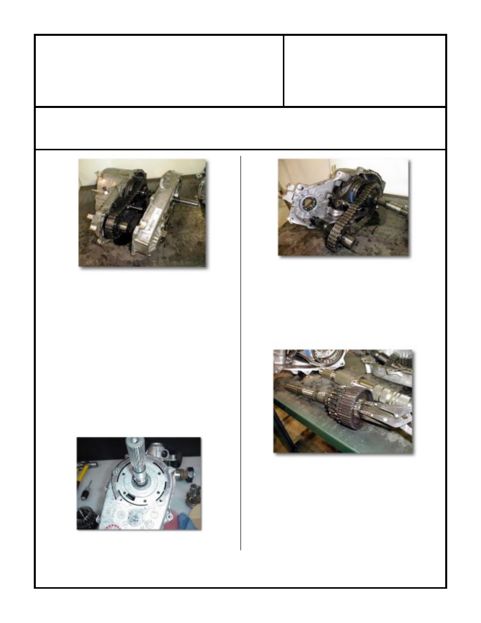
(Fig. 10) Oil Pump Removal
(Fig. 9) Rear Case Half Removal
(11) Remove the rear case bolts. A 10mm 12 pt. socket is needed
for the spline head bolt and a 15mm socket for the remaining
bolts.
NOTE:
The two black oxide finished bolts are located at
the case dowel positions and require a washer under them.
(12) Start to remove the rear case from the front case by inserting
pry bars at the cast-in locations ONLY!
(Fig. 9)
(a) Pry apart evenly to break the sealer bead along the case
mating surfaces.
(13)
(Fig. 10)
The oil pump pickup tube is not accessible from the
back of the case until the back half of the case has been taken
off far enough to disengage the pump drive splines on the stock
output shaft.
At that time, you can either slide the pump up on
the housing and remove the pump pickup tube or just remove the
pump and pickup tube complete with the rear case half.
(a) Inspect the pickup tube "o-ring" in the pump and replace if
needed. The same goes for the front shaft seal in the pump.
Do NOT disassemble the pump; it is not a serviceable item.
(b) Remove, clean and inspect the inner case for wear.
(Fig. 11) Front Drive Chain & Shaft Removal
(14) Front output shaft removal:
(a) Pull the front output shaft out of the front bearing.
(Fig. 11)
(b) Slide drive chain off the rear output shaft and remove both
shaft and chain for cleaning & inspection.
(15) Rear output shaft removal:
(a) Grasp the main shaft and remove the shaft, drive sprocket
and mode hub assembly.
(Fig. 12) Front Drive Chain & Shaft Removal
(16) Output shaft disassembly:
(a) Remove the mode hub retaining ring with heavy duty snap
ring pliers.
(Fig. 12)
(b) Slide remaining components, mode hub & drive sprocket off
shaft.
(17) This is as far into the case you need to go unless you find foreign
material inside usually caused by a worn or stretched drive
chain. You will need to be the judge.