Advance adapters inc, Np231 short shaft "fixed yoke" kit – Advance Adapters 50-7906B User Manual
Page 3
ADVANCE ADAPTERS INC.
P/N: 50-7905, 50-7906 & 50-7906B
P.O. Box 247, 4320 Aerotech Center Way
New Item: (12/98)
Paso Robles, CA 93447
PAGE 3 OF 12
Telephone: (800) 350-2223
Fax: (805) 238-4201
Page Rev. Date:
07-31-07
SPECIAL NOTE:
The components packaged in this kit have been assembled and machined for specific type of conversions. Modifications to any of the
components will void any possible warranty or return privileges. If you do not fully understand modifications or changes that will be required to complete your conversion,
we strongly recommend that you contact our sales department for more information. This instruction sheet is only to be used for the assembly of Advance Adapter
components. We recommend that a service manual pertaining to your vehicle be obtained for specific torque values, wiring diagrams and other related equipment.
These manuals are normally available at automotive dealerships and parts stores.
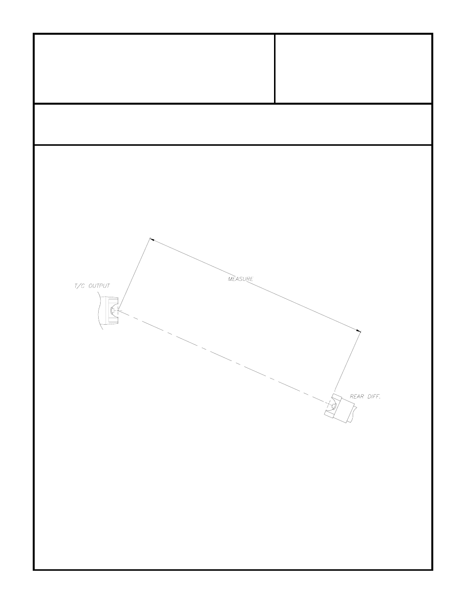
DRIVE SHAFT MODIFICATION:
This job should be performed by a local driveline repair shop capable of balancing the finished assembly. (Use a C.V.
joint & long slip spline style shaft assembly.)
With the vehicle finished and on the ground, measure a straight line between the transfer case output yoke and the rear
pinion yoke center mating flanges.
(Fig. A)
NP231 SHORT SHAFT "FIXED YOKE" KIT
(Fig. A)
For proper C.V. type drive shaft operation, the rear differential should be pointed at the transfer case output yoke under
normal driving load.
If install is performed on jack stands, make sure you have supported the vehicle well!
Place the transfer case range selector in the 4L position.
Remove front & rear drive shafts and begin at the disassembly procedures. (Step 1, Fig. 1)