Operation, Operating procedures 8-1, Control stations 8-1 – Snorkel MHP34J(Bi-Energy Option) User Manual
Page 45: Emergency stopping 8-1, Operating procedures, 8-1, Control stations, 8-1, Emergency stopping, 8-1, Operation, 8-1, Sandblast protection kit, 8-1, Operating procedures -1
8. Operation
■
Operating Procedures
This chapter explains how to properly start and op-
erate an MHP12/34J. Read and understand all the
previous chapters in this manual before you begin
to operate an MHP12/34J.
If you use the MHP12/34J for painting be sure
the optional sandblast protection kit is
installed to protect the hydraulic cylinder
rods from paint. Do not leave the MHP12/34J
engine running if you are sandblasting. Sand
drawn into the air intake can erode engine
parts.
■
Control Stations
An MHP12/34J can be operated from the ground
control box or from the platform control box. There
are basically two differences between ground con-
trol and platform control operations, both are safety
related:
1. The ground control box can override the
platform control box at any time. If a person
operating the machine from the platform
becomes incapacitated, a person on the
ground can always take over machine control.
2. The outriggers can only be selected from the
ground control box and only when the
booms are in the stowed position.
The MHP12/34J is not Electrically Insulated.
Death or Serious Injury to operating
personnel, can occur if the machine should
come into contact with energized electrical
wires during operation.
DO NOT attempt to operate the MHP12/34J
ground controls if the platform, booms, or
any other conducting part of an MHP12/34J
is in contact with energized electrical wires
or if there is an immediate danger of such
contact.
NOTE
See the "Electrical Hazard" section, in this
manual for a complete explanation of the hazards
concerning electricity.
■
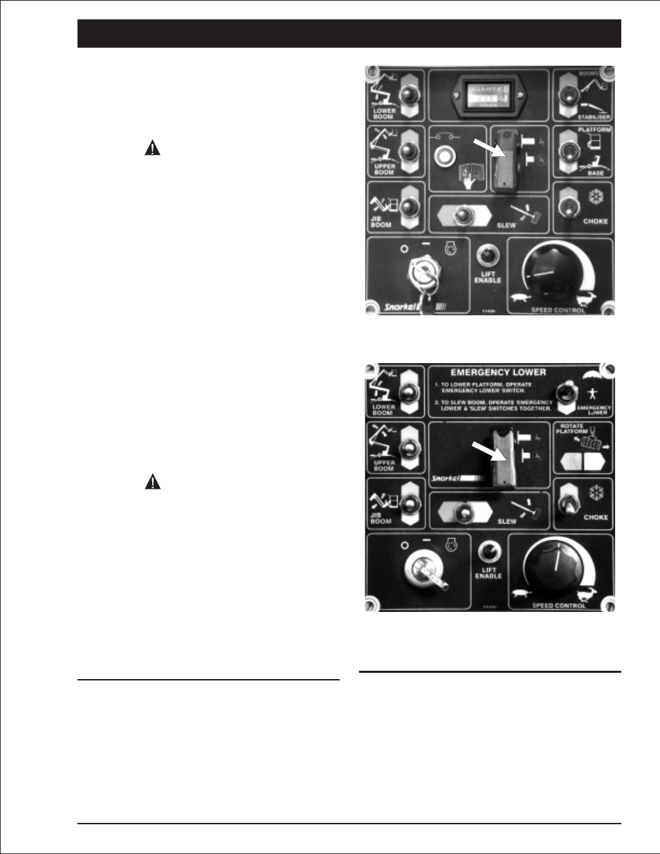
Emergency Stopping
To stop an MHP12/34J, press the Emergency
Stop switch cover down on either of the two
EMERGENCY STOP switches at the ground con-
trol box or at the platform control box.
Figure 8.1 - Ground Control Box Emergency
Stop Switch Location.
Figure 8.2 - Platform Control Box Emergency
Stop Switch Location.
NOTE
For a complete discussion of the Emergency
Stop switches, see “Controls” chapter 6, in this
manual.
MHP12/34J – 11447A
page 8 - 1
CAUTION
DANGER