Product manual – Class1 119327 - VDR system 118093 118097 118551 118620 119375 - EXTERNAL User Manual
Page 15
FORM-ENG-0018 REV A 05-27-03
607 NW 27th Ave
Ocala, FL 34475
Ph: 352-629-5020 or 1-800-533-3569
Fax : 352-629-290 or 1-800-520-3473
PRODUCT MANUAL
PAGE
14
OF 26
DATE
10/17/2011
PRODUCT GROUP
ES-Key
P/N
119914, 118093, 118620, 118551, 119375
REV
1.70
PRODUCT
Vehicle Data Recorder and Seat Belt Warning system
BY
AMS
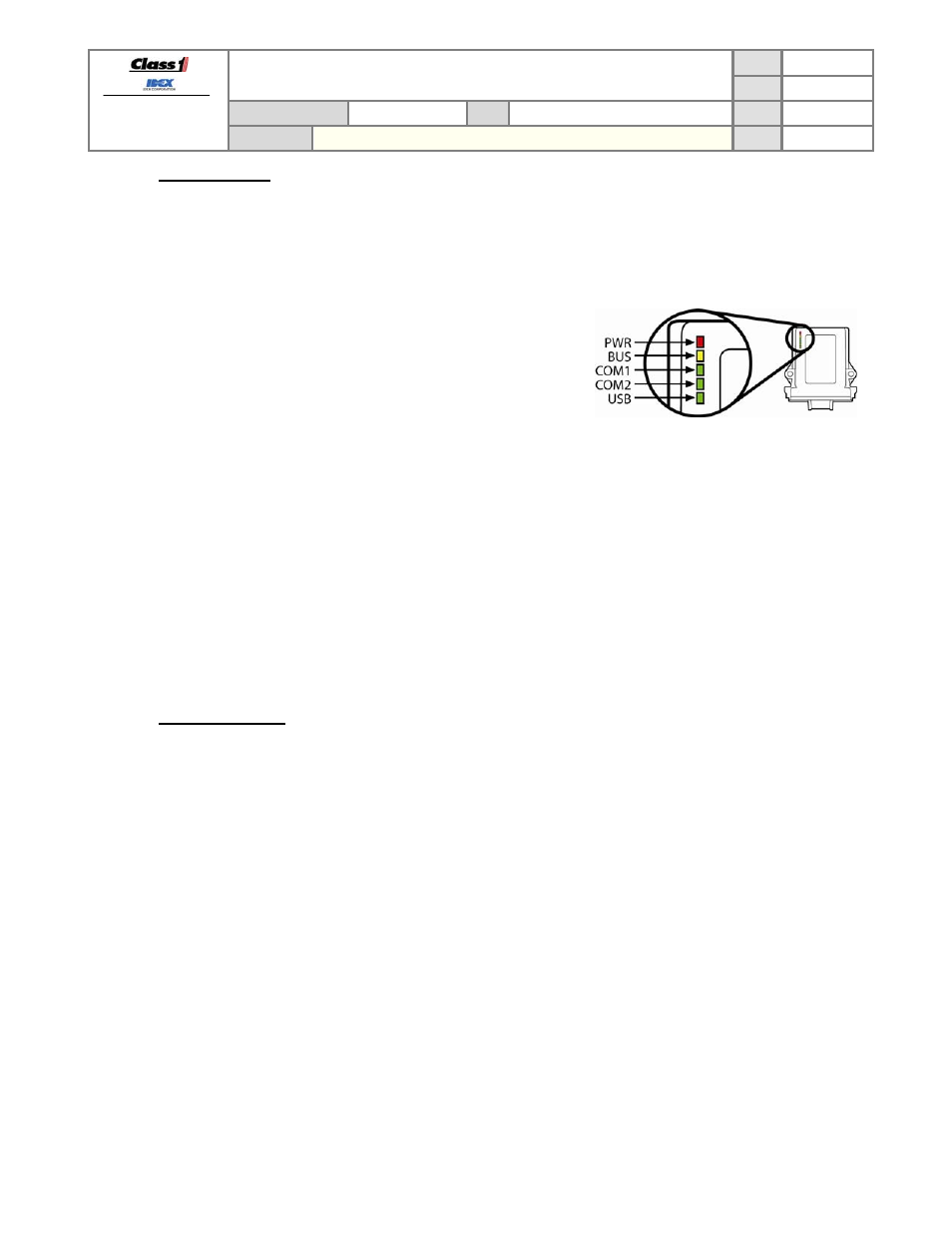
5.4.2. Diagnostic
LEDs
The Vehicle Data Recorder has 5 LEDs which are intended for
quick diagnostic evaluation and are viewable through the amber
enclosure.
PWR – red LED is ON when the VDR module has proper voltage
after the internal fuse.
BUS – yellow LED is on when the VDR module has proper
voltage at the connector (pins 1, and 12 – see
section 9.4).
COM1 – green LED is ON solid when CAN communication is
good with the Seat Belt Warning system.
COM2 – green LED is ON solid when CAN communication is
good with the engine/transmission system.
USB – green LED is ON solid when the VDR module has made
a valid connection to the host computer running the VDR
Management software.
The CAN communication LEDs (COM1, COM2) will flash to indicate an error.
Slow flash (once per second) indicates that the CAN bus is good but the VDR is not receiving messages
from the Seat Belt Warning system.
Fast flash (five times per second) indicates that there is an issue with the CAN bus. Verify that terminating
resistor(s) are installed, verify the connection to the CAN bus is properly connected, verify that CAN H and
CAN L are not shorted together or to ground or power, etc.
5.4.3. OEM
responsibility
The Vehicle Data Recorder must be properly powered and connected to the associated CAN buses to record NFPA
data correctly. It is the OEM’s responsibility to ensure that the VDR is connected properly and the potential for
tampering is minimized.