Operation manual – Class1 114356 - ITL 4LT with 1-wire and CAN COM 113739 114378 User Manual
Page 20
FORM-ENG-0018 REV A 05-27-03
PAGE
19 of 22
S U I T A B L E F O R E X T E R N A L D I S T R I B U T I O N
OPERATION MANUAL
DATE
10/23/2007
PRODUCT GROUP
ITL
P/N
12V: 113739 ; 24V: 114378
REV
1.20
607 NW 27th Ave
Ocala, FL 34475
Ph: 352-629-5020 or 1-800-533-3569
Fax : 352-629-2902 or 1-800-520-3473
PRODUCT
4 LIGHT INTELLI-TANK DISPLAY WITH 1-wire and CAN
BY
AMS
DATASHEET
P/N:114356 -
UNCONTROLLED
IN
PRINTED
FORMAT
-
P
RINTED
:
10/24/07
Condition
Visual
Evaluate
Master Tank level unit
does not change when
actual tank level is
changing.
No picture
Check transducer wiring. Ensure transducer signal voltage (Pin C) is varying. If it
does, check for same signal changes at Pin 6 of tank level connector (if it is not
the same repair wiring). If signal is good at both locations try re-calibrating.
Remote Tank level unit
does not follow Master
display.
No picture
Perform self test. If self test is good, check pin 4 (data line) for continuity and
insure it is not shorted to ground or power. Insure data line is not routed near
noisy power or RF sources.
Unit fails self test, LED 2
on.
Check pin 4 (data line) for continuity and insure it is not shorted to ground or
power.
No passwords are
accepted.
If the display issues the “wave off” after entering a password, insure the display is
installed upright. During power-up the display should cycle on each LED
individually starting with the bottom LED.
Check that the left and right magnetic switches are recognized by activating each
switch and verifying that the associated LEDs illuminate.
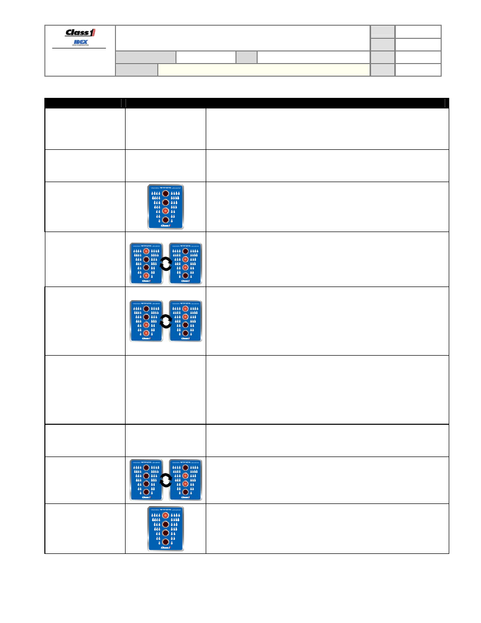
The bottom two LEDs
are on and occasionally
they go out and the top
two flash and then return
to the bottom two LEDs
on (or vice-versa).
(REMOTE).
Check for large noise spikes on the 1-wire data line.
Insure that the display’s ground potential is the same as the Master’s.
Insure that the data line is not chaffed and making contact with other electrical
wires.
The points calibrated
seemed to have
changed.
No picture
Self test the display to check for any malfunctions.
Check the pressure transducer for problems.
Recalibrate the display and take a voltage reading from the transducer (pin 7 on
the display’s connector) at each calibration point. When the calibration points
again look wrong check the voltages at those points and determine if they are the
same as the voltage reading taken during calibration.
Unit will not dim display.
No picture
Insure the Dim input voltage on Pin 3 is at least 9V. Recalibrate dim setting
(RLLR LLLR). If display does not dim LEDs while in dim calibrate mode, replace
display.
The middle two LEDs
are flashing together.
A calibration was started on the display but not completed correctly. Set the
display to a REMOTE display (LRLR LRLR) or calibrate it as a MASTER (follow
calibration steps exactly).
Top LED is the only LED
illuminated.
The display has had a unit type memory error.
Attempt to set the display back to REMOTE or MASTER as required.