Electrical system manager ii – Class1 ESM3 User Manual
Page 7
7
Electrical System Manager II
COM
N O N C
COM
N O N C
COM
N O N C
COM
N O N C
COM
N O N C
COM
N O N C
COM
N O N C
COM
N O N C
1
2
3
4
5
6
7
8
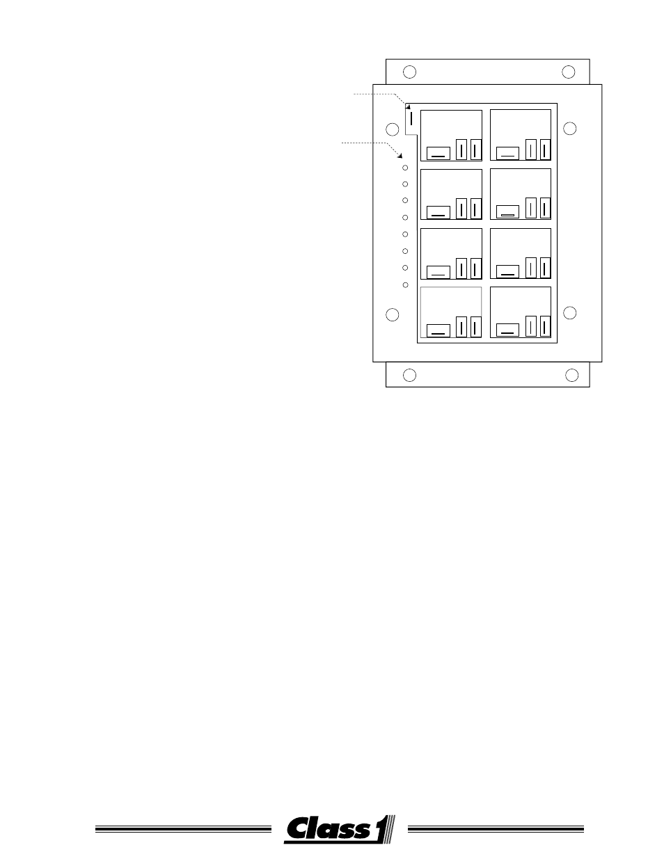
Relay LED©s
Relay Coil Input
1
2
3
4
5
6
7
8
The Electrical System Manager II is equipped
with 8 Printed Circuit Board Relays mounted in
an enclosure with the load manager. The re-
lay coil input tab should be grounded for nor-
mal installations. The common and output tabs
on each relay readily allow for custom installa-
tions.
See also other documents in the category Class1 For the car:
- 4 output tank level (5 pages)
- Digital Aerial Warning Display (6 pages)
- Digital Air Minder (8 pages)
- Digital Clock (1 page)
- Digital Display (35 pages)
- Flowminder 102046 - SSD Digital Flow Meter (9 pages)
- Digital Oxygen Remaining (6 pages)
- Digital Pressure Gauge (6 pages)
- Digital Tank Level Display (5 pages)
- Electrical System Manager (15 pages)
- Electronic Fire Commander (8 pages)
- ENFO III (4 pages)
- ENFO IV - 1 page (1 page)
- ENFO IV (10 pages)
- Engine status center (9 pages)
- Engine status OEM menu (3 pages)
- ES-Key-USM (30 pages)
- Intelli Tank 4 light driver module (9 pages)
- Intelli Tank level display with drip empty (16 pages)
- Intelli-Tank (15 pages)
- Total System Manager (12 pages)
- Total System Manager (19 pages)
- Vernier Throttle for CAT- new (8 pages)
- Vernier Throttle for CAT (12 pages)
- Vernier Throttle for Cummins (9 pages)
- Digital Pressure Service & Calibration (5 pages)
- 109395 - ITL 4LT with 1-wire COM 106296 106299 - 1page (1 page)
- Throttle Information Reference (24 pages)
- ITL Tank Level Driver Module 107451 (9 pages)
- ITL Mini Remote Driver one-page_manual 112648 (1 page)
- Throttle Interface CAT 105216 (8 pages)
- Pump Throttle Electric Cotnrol Series 2 (14 pages)
- 107490 - UNI-Governor 107396 107269 software v 6 00 (38 pages)
- FoamLogix 2.1A & 1.7AHP REV E (96 pages)
- EZFill Foam Refill (46 pages)
- Digital speedometer (4 pages)
- 106759 - ITL 4LT with 1-wire COM 106296 106299 (18 pages)
- 114356 - ITL 4LT with 1-wire and CAN COM 113739 114378 (24 pages)
- 115355 - ITL 4LT with 1-wire and CAN COM 113739 114378 - Page (1 page)
- 117155 - TPG Governor - 117684 EXTERNAL (30 pages)
- 117155 - TPG Governor - 117685 (2 pages)
- 118253 - ITL40 108404-XX - Full (26 pages)
- 118252 - ITL40 118404-XX - Quick Start (1 page)
- 118712 - TPG+ Governor - 118710 (2 pages)