Main and isolated battery config, Main and isolated battery configuration, Electrical system manager – Class1 ESM3 User Manual
Page 6
6
105519 08172000
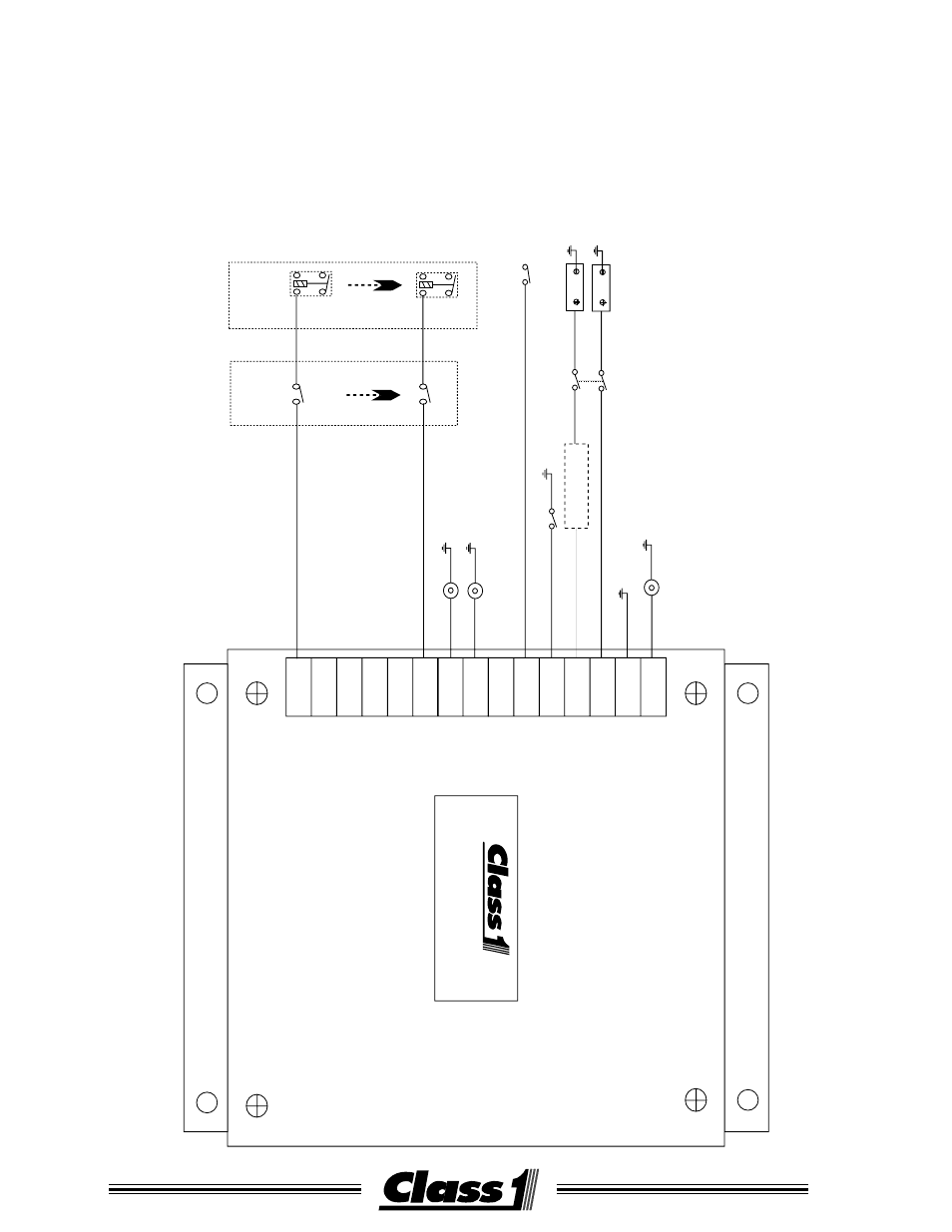
Jumper J9 placed in ISO BATTERY position and SW1 switch 1 is turned ON.
The system manager will operate in main and isolated battery mode.
A separate input for the isolated battery is located at T12 and an output for
Isolated Battery Low is located at T7.
This provides for six load control outputs (T1-T6) which can be sequenced
and shed.
MAIN AND ISOLATED BATTERY CONFIGURATION
ELECTRICAL SYSTEM
MANAGER
Over Voltage Lt
Ignition Sw
Main Batt
Isolated Batt
Shed Enable Switch
Master Sw
connected only
when ignition on
Rly 1
Rly 6
Load Sw 1
Load Sw 6
Dash Switches
Load Relays
Battery Warning Lt
Isolated Batt Lt
T 1
T 9
T 5
T 13
T 3
T 11
T 7
T 15
T 2
T 10
T 6
T 14
T 4
T 12
T 8
See also other documents in the category Class1 For the car:
- 4 output tank level (5 pages)
- Digital Aerial Warning Display (6 pages)
- Digital Air Minder (8 pages)
- Digital Clock (1 page)
- Digital Display (35 pages)
- Flowminder 102046 - SSD Digital Flow Meter (9 pages)
- Digital Oxygen Remaining (6 pages)
- Digital Pressure Gauge (6 pages)
- Digital Tank Level Display (5 pages)
- Electrical System Manager (15 pages)
- Electronic Fire Commander (8 pages)
- ENFO III (4 pages)
- ENFO IV - 1 page (1 page)
- ENFO IV (10 pages)
- Engine status center (9 pages)
- Engine status OEM menu (3 pages)
- ES-Key-USM (30 pages)
- Intelli Tank 4 light driver module (9 pages)
- Intelli Tank level display with drip empty (16 pages)
- Intelli-Tank (15 pages)
- Total System Manager (12 pages)
- Total System Manager (19 pages)
- Vernier Throttle for CAT- new (8 pages)
- Vernier Throttle for CAT (12 pages)
- Vernier Throttle for Cummins (9 pages)
- Digital Pressure Service & Calibration (5 pages)
- 109395 - ITL 4LT with 1-wire COM 106296 106299 - 1page (1 page)
- Throttle Information Reference (24 pages)
- ITL Tank Level Driver Module 107451 (9 pages)
- ITL Mini Remote Driver one-page_manual 112648 (1 page)
- Throttle Interface CAT 105216 (8 pages)
- Pump Throttle Electric Cotnrol Series 2 (14 pages)
- 107490 - UNI-Governor 107396 107269 software v 6 00 (38 pages)
- FoamLogix 2.1A & 1.7AHP REV E (96 pages)
- EZFill Foam Refill (46 pages)
- Digital speedometer (4 pages)
- 106759 - ITL 4LT with 1-wire COM 106296 106299 (18 pages)
- 114356 - ITL 4LT with 1-wire and CAN COM 113739 114378 (24 pages)
- 115355 - ITL 4LT with 1-wire and CAN COM 113739 114378 - Page (1 page)
- 117155 - TPG Governor - 117684 EXTERNAL (30 pages)
- 117155 - TPG Governor - 117685 (2 pages)
- 118253 - ITL40 108404-XX - Full (26 pages)
- 118252 - ITL40 118404-XX - Quick Start (1 page)
- 118712 - TPG+ Governor - 118710 (2 pages)