Infinity supported application 11 – AEM Infinity Supported Applications - Dodge HEMI Engine User Manual
Page 11
Infinity Supported Application
11
© 2014 AEM Performance Electronics
Infinity
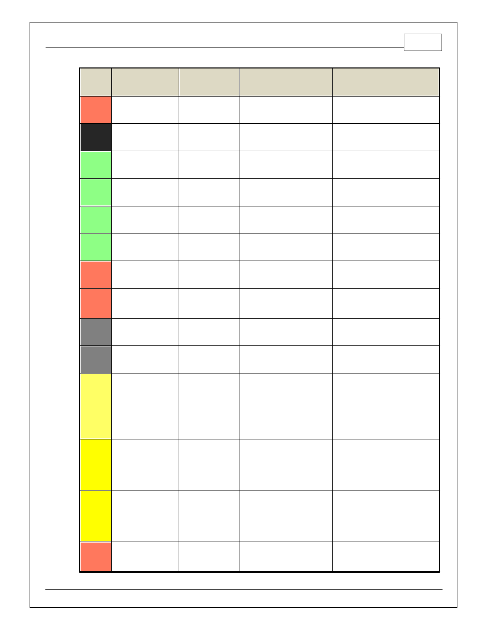
Pin
Hardware Reference
7100-XXXX-62
7101-XXXX-63
Function
Hardware Specification
Notes
C2-2
DBW2 Motor -
DBW Motor Control
Close
5.0A max Throttle Control Hbridge
Driv e
+12V to close
C2-3
Power Ground
Ground
Power Ground
Connect directly to battery ground.
C2-4
Injector 7
Injector 7
Saturated or peak and hold, 3A
max continuous
Injector 7
C2-5
Injector 8
Injector 8
Saturated or peak and hold, 3A
max continuous
Injector 8
C2-6
Injector 9
Injector 9
Saturated or peak and hold, 3A
max continuous
Injector 9
C2-7
Injector 10
Injector 10
Saturated or peak and hold, 3A
max continuous
Injector 10
C2-8
Power Ground
Ground
Power Ground
Connect directly to battery ground.
C2-9
+12V
+12V In
12 v olt power f rom relay
12 v olt power f rom relay . Relay must
be controlled by +12V Relay Control
signal, pin C1-29 abov e.
C2-10
Injector 11
Injector 11
Saturated or peak and hold, 3A
max continuous
Not used
C2-11
Injector 12
Injector 12
Saturated or peak and hold, 3A
max continuous
Not used
C2-12
Analog_In_17
A/C Analog Request
12 bit A/D, 100K pullup to 5V
0–5V analog signal. Use +5V Out pins
as power supply and Sensor Ground
pins as the low ref erence. Do not
connect signals ref erenced to +12V as
this can permanently damage the ECU.
See Setup Wizard Input Functions page
f or input selection. See AC_Request_In
1-axis table f or activ ation logic.
C2-13
Analog_In_18
DBW_APP1 [%]
12 bit A/D, 100K pullup to 5V
0–5V analog signal. Use +5V Out pins
as power supply and Sensor Ground
pins as the low ref erence. Do not
connect signals ref erenced to +12V as
this can permanently damage the ECU.
C2-14
Analog_In_19
DBW_APP2 [%]
12 bit A/D, 100K pullup to 5V
0–5V analog signal. Use +5V Out pins
as power supply and Sensor Ground
pins as the low ref erence. Do not
connect signals ref erenced to +12V as
this can permanently damage the ECU.
C2-15
Analog_In_Temp_4
Charge Out
Temperature
12 bit A/D, 2.49K pullup to 5V
See ChargeOutTemp [C] table f or
calibration data and ChargeOutTemp [C]
f or channel data.