Pinout 9 – AEM Infinity Supported Applications - BMW 1995 E36 M3 User Manual
Page 9
PINOUT
9
© 2014 AEM Performance Electronics
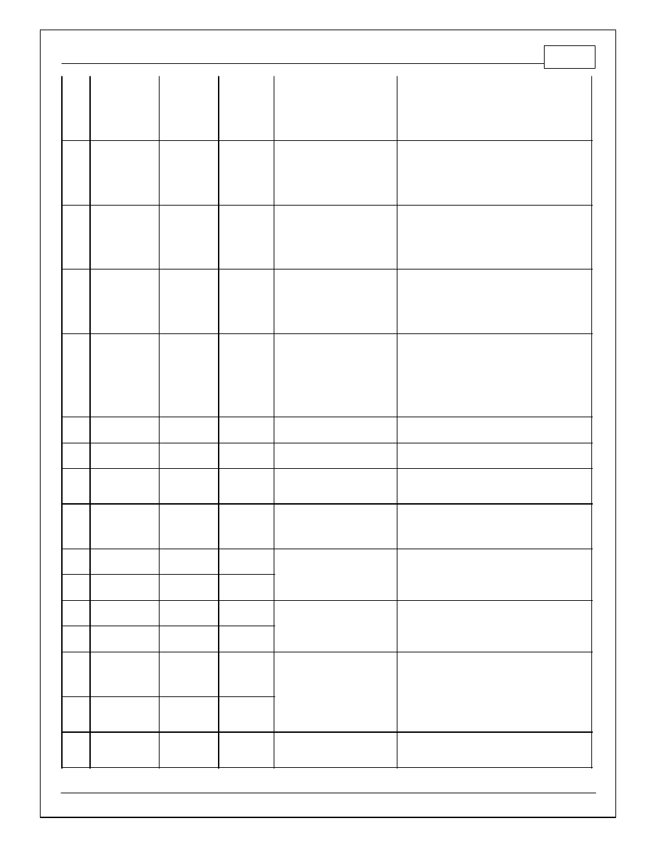
C1-36
Analog_In_8
MAP Sensor
to MAP
sensor
12 bit A/D, 100K pullup to 5V
0-5V analog signal. Use +5V Out pins as power supply
and Sensor Ground pins as the low ref erence. Do not
connect signals ref erenced to +12V as this can
permanently damage the ECU. See the Setup Wizard
Set Manif old Pressure page f or setup and calibration.
Monitor the MAP [kPa] channel.
C1-37
Analog_In_9
Fuel Pressure
12 bit A/D, 100K pullup to 5V
0-5V analog signal. Use +5V Out pins as power supply
and Sensor Ground pins as the low ref erence. Do not
connect signals ref erenced to +12V as this can
permanently damage the ECU. See the Setup Wizard
Fuel Pressure page f or setup and calibration. Monitor
the FuelPressure [psig] channel.
C1-38
Analog_In_10
Baro Sensor
12 bit A/D, 100K pullup to 5V
0-5V analog signal. Use +5V Out pins as power supply
and Sensor Ground pins as the low ref erence. Do not
connect signals ref erenced to +12V as this can
permanently damage the ECU. See the Setup Wizard
Barometric Pressure page f or setup and calibration.
Monitor the BaroPress [kPa] channel.
C1-39
Analog_In_11
Shif t Switch
Input
12 bit A/D, 100K pullup to 5V
0-5V analog signal. Use +5V Out pins as power supply
and Sensor Ground pins as the low ref erence. Do not
connect signals ref erenced to +12V as this can
permanently damage the ECU. See the 1D lookup
table 'Shif tSwitch' f or setup. Also assignable to
multiple f unctions. See Setup Wizard f or details.
C1-40
Analog_In_12
Mode Switch
12 bit A/D, 100K pullup to 5V
0-5V analog signal. Use +5V Out pins as power supply
and Sensor Ground pins as the low ref erence. Do not
connect signals ref erenced to +12V as this can
permanently damage the ECU. See the 1D lookup
table 'ModeSwitch' f or input state. A multi-position
rotary switch such as AEM P/N 30-2056 is
recommended. Also assignable to multiple f unctions.
See Setup Wizard f or details.
C1-41
+5V_Out_1
+5V Out
59
Regulated, f used +5V supply f or
sensor power
Analog sensor power
C1-42
+5V_Out_1
+5V Out
to MAP
sensor
Regulated, f used +5V supply f or
sensor power
Analog sensor power
C1-43
HighsideSwitch_1
HS1 (switched
12V)
0.7A max, High Side Solid State
Relay
See Setup Wizard page 'HighSide Assigment Tables' f or
conf iguration options. See 2D lookup table 'HS1_Table'
f or activ ation settings.
C1-44
HighsideSwitch_0
HS0 (switched
12V)
0.7A max, High Side Solid State
Relay
See Setup Wizard page 'HighSide Assigment Tables' f or
conf iguration options. See 2D lookup table 'HS0_Table'
f or activ ation settings.
C1-45
Crank Position
Sensor VR+
Crank Position
Sensor VR+
16
Dif f erential Variable Reluctance
Zero Cross Detection
See Setup Wizard page Cam/Crank f or options.
C1-46
Crank Position
Sensor VR-
Crank Position
Sensor VR-
43
C1-47
Cam Position
Sensor 1 VR-
Cam Position
Sensor 1 VR-
Dif f erential Variable Reluctance
Zero Cross Detection
See Setup Wizard page Cam/Crank f or options.
C1-48
Cam Position
Sensor 1 VR+
Cam Position
Sensor 1 VR+
C1-49
VR+_In_2
Non Driv en
Lef t Wheel
Speed Sensor
+
Dif f erential Variable Reluctance
Zero Cross Detection
See Non Driv en Wheel Speed Calibration in the Setup
Wizard Vehicle Speed page.
C1-50
VR-_In_2
Non Driv en
Lef t Wheel
Speed Sensor -
C1-51
VR-_In_3
Driv en Lef t
Wheel Speed
Sensor -
Dif f erential Variable Reluctance
Zero Cross Detection
See Driv en Wheel Speed Calibration in the Setup
Wizard Vehicle Speed page.