Page 20 of 21 – AEM 30-6821 Series 2 Plug & Play EMS User Manual
Page 20
Page 20 of 21
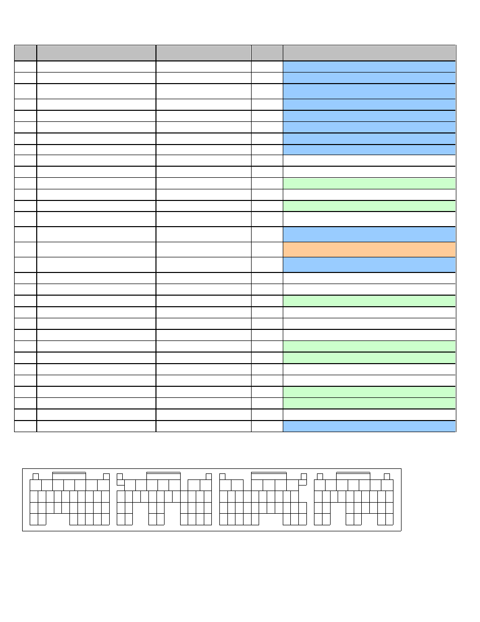
Pin
2004 STI 2.5L / 2005-2006 STI 2.5L
AEM EMS
30-6820
EMS
I/O
EMS pin description
D1
GND (control systems)
Power Ground
In
Dedicated, also A34,B1, B4,B12,B31,C32,C33,D2,D7,D31
D2
GND (control systems)
Power Ground
In
Dedicated, also A34,B1, B4,B12,B31,C32,C33,D1, D7,D31
D3
Electronic Throttle control GND
(sensor)
Electronic Throttle Ground
Out
Dedicated
D4
Electronic Throttle control motor (-)
Electronic Throttle Motor -
Out
Dedicated, ETC system output
D5
Electronic Throttle control motor (+)
Electronic Throttle Motor +
Out
Dedicated, ETC system output
D6
Electronic Throttle control Motor Power
Electronic Throttle Power
In
Dedicated, ETC power
D7
GND (Injectors)
Power Ground
In
Dedicated, also A34,B1, B4,B12,B31,C32,C33,D1,D2,D31
D8
Starter switch
Main Relay circuit (Switch #1)
In
Dedicated
D9
Neutral Position switch
---
Not Used
D10
Power Steering oil pressure switch
---
Not Used
D11
Rear Defogger switch
Switch #4
In
Available, switch should connect to GND when closed
D12
(not used by stock ECU)
---
Not Used
D13
Blower Fan switch
Switch #5
In
Available, switch should connect to GND when closed
D14*
Test Mode Connector / Ignition Switch*
--- / Main Relay circuit
(Switch1)*
*
Not Used
D15*
Ignition Switch / Test Mode Connector*
Main Relay circuit (Switch 1) / -
-- *
In*
Dedicated
D16*
AC Switch / Main Relay control*
Switch 6 / Main Relay circuit
(Coil 7) *
In*
PnP for A/C request switch
D17*
Main Relay control / AC Switch*
Main Relay circuit (Coil 7) /
Switch 6 *
Out*
Dedicated, activates main relay with switched GND
D18
---
---
Not Used
D19
---
---
Not Used
D20
SSM / GST communication line
EGT #2
In
Available, jumper set for 0-5V input
D21
---
---
Not Used
D22
---
---
Not Used
D23
---
---
Not Used
D24
Blow-by Leak diagnosis signal
EGT #3
In
Available, jumper set for 0-5V input
D25
Rear Oxygen sensor Signal
Lambda #2
In
Available, 0-5V O2 #2 signal
D26
---
---
Not Used
D27
---
---
Not Used
D28
Fuel Pump control unit Signal 2
Low Side Driver #5
Out
Available, can be used for Switched Ground (1.5A max)
D29
--
EGT #4
In
Available, jumper set for 0-5V input
D30
---
---
Not Used
D31
Rear Oxygen sensor Shield
Power Ground
Out
Dedicated, also A34,B1, B4,B12,B31,C32,C33,D1,D2,D7
1
2
3
4
5
6
7
8
9
10
11
12
13
14
15
16
18
19
20
21
22
23
Connector D
Connector C
Connector B
Connector A
Wire View Of AEM EMS
29
32
30
31
28
17
24
25
26
27
33
34
17 16 15 14 13 12 11 10
31
23
35 34
26
27
32
21
22
20
30
7
6
5
3
4
2
1
8
9
28
29
18
19
24
25
33
8
9
10
11
12
13
14
15
16
18
28
27
22
32
34
25
26
24 23
30
31
29
20
21
19
6
5
4
3
2
1
7
17
35
33
8
9
10
11
12
13
14
15
16
17
18
26
31
22
28
30
25 24
23
27
20
21
19
7
6
5
4
3
2
1
29