Page 17 of 21 – AEM 30-6821 Series 2 Plug & Play EMS User Manual
Page 17
Page 17 of 21
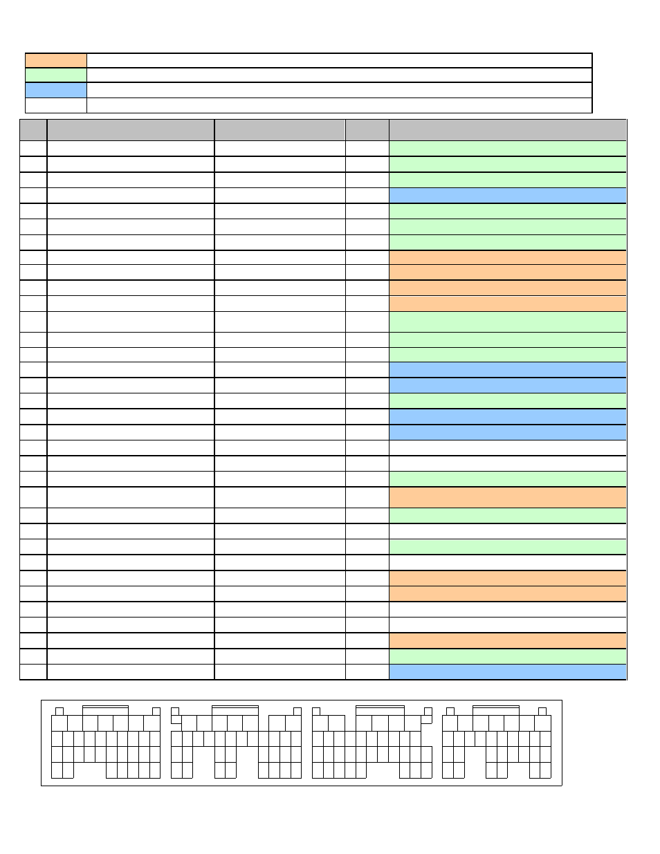
Connection Diagram for EMS P/N 30-6820
PnP
The Plug and Play system comes with this configured for proper operation of this device. It is available for reassignment.
Available
The function is not currently allocated and is available for use
Dedicated
The location is fixed and cannot be changed
Not used
The AEM EMS does not use this pin location for this application
Pin
2004 STI 2.5L / 2005-2006 STI 2.5L
AEM EMS
30-6820
EMS
I/O
EMS pin description
A1
Clutch Switch
Switch 3
In
Available, switch should connect to +12V when closed
A2
Front Oxygen Sensor Heater (Signal 2)
Injector 5
Out
Available, can be used for additional injectors (1.5A max)
A3
Front Oxygen Sensor Heater (Signal 1)
Injector 6
Out
Available, can be used for additional injectors (1.5A max)
A4
---
Sensor Ground
Out
Dedicated, sensors only, connects to pin C31
A5
---
O2 #1
In
Available, 0-5V O2 sensor #1, connects to pin A26
A6
GND (Front Oxygen A/F Heater 2)
Injector 7
Out
Available, can be used for additional injectors (1.5A max)
A7
GND (Front Oxygen A/F Heater 1)
Injector 8
Out
Available, can be used for additional injectors (1.5A max)
A8
Tumble Generator Valve RH (close)
Idle 6
Out
PnP for TGV
A9
Tumble Generator Valve RH (open)
Idle 5
Out
PnP for TGV
A10
Tumble Generator Valve LH (close)
Idle 8
Out
PnP for TGV
A11
Tumble Generator Valve LH (open)
Idle 7
Out
PnP for TGV
A12
Pressure control solenoid valve (fuel
tank)
Low Side 3
Out
Available, can be used for Switched Ground (1.5A max)
A13
Drain Valve
Low Side 2
Out
Available, can be used for Switched Ground (1.5A max)
A14
Purge Control solenoid valve
Low Side 4
Out
Available, can be used for Switched Ground (1.5A max)
A15
Main light ("Cruise" lamp on dash)
Cruise light
Out
Dedicated, ETC system output
A16
Cruise Set light ("Set" lamp on dash)
Set light
Out
Dedicated, ETC system output
A17
Malfunction Indicator Lamp
Low Side 10
Out
Available, can be used for Switched Ground (1.5A max)
A18
Oil flow control solenoid (RH) Signal (+)
+12V Switched Ignition Power
Out
Dedicated,
also connects to A19, B5, B6
A19
Oil flow control solenoid (LH) Signal (+)
+12V Switched Ignition Power
Out
Dedicated,
also connects to A18, B5, B6
A20
---
---
Not Used
A21
---
---
Not Used
A22
Alternator
Low Side 1
Out
Available, can be used for Switched Ground (1.5A max)
A23
Engine Speed Output (to OEM
tachometer)
Tacho out (LS7)
Out
PnP for Tachometer
A24
Fuel Tank sensor control valve
Low Side 11
Out
Available, can be used for Switched Ground (1.5A max)
A25
Front Oxygen sensor shield
---
Not Used
A26
Front Oxygen sensor signal (-)
O2 #1
In
Available, 0-5V O2 sensor #1, connects to pin A5
A27
---
---
Not Used
A28
Oil flow control solenoid (RH) Signal (-)
Injector 9
Out
PnP for VVC #1 (Active Valve Control Solenoid)
A29
Oil flow control solenoid (LH) Signal (-)
Injector 10
Out
PnP for VVC #2 (Active Valve Control Solenoid)
A30
---
---
Not Used
A31
---
---
Not Used
A32
Wastegate Control solenoid valve
PW 2
Out
PnP for Boost Control Solenoid
A33
Front Oxygen sensor signal (+)
ADCR13
Out
Available, 0-5V sensor
A34
Engine Ground
Power Ground
In
Dedicated, also B1,B4,B12,B31,C32,C33,D1,D2,D7,D31
1
2
3
4
5
6
7
8
9
10
11
12
13
14
15
16
18
19
20
21
22
23
Connector D
Connector C
Connector B
Connector A
Wire View Of AEM EMS
29
32
30
31
28
17
24
25
26
27
33
34
17 16 15 14 13 12 11 10
31
23
35 34
26
27
32
21
22
20
30
7
6
5
3
4
2
1
8
9
28
29
18
19
24
25
33
8
9
10
11
12
13
14
15
16
18
28
27
22
32
34
25
26
24 23
30
31
29
20
21
19
6
5
4
3
2
1
7
17
35
33
8
9
10
11
12
13
14
15
16
17
18
26
31
22
28
30
25 24
23
27
20
21
19
7
6
5
4
3
2
1
29