Page 18 of 21 – AEM 30-6821 Series 2 Plug & Play EMS User Manual
Page 18
Page 18 of 21
Pin
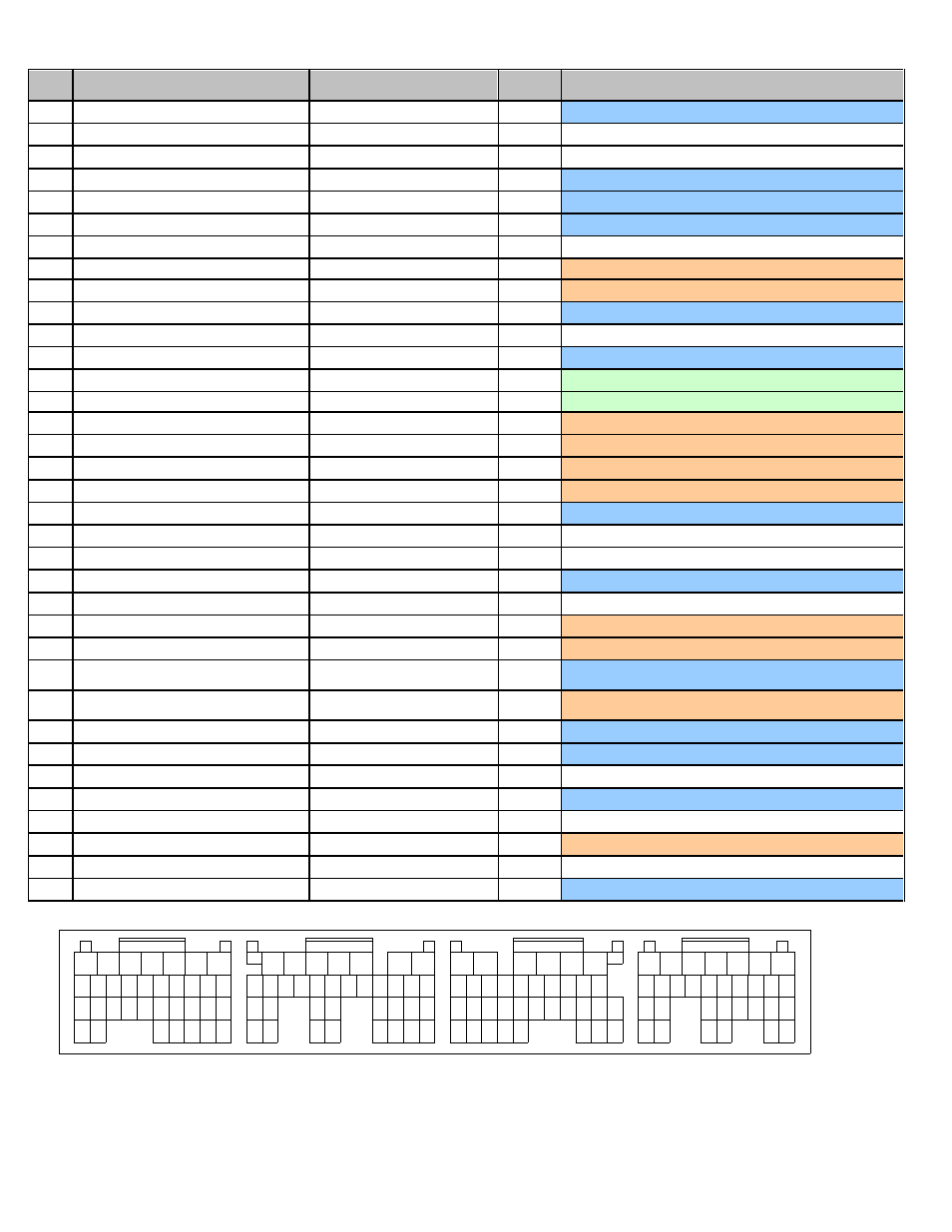
2004 STI 2.5L / 2005-2006 STI 2.5L
AEM EMS
30-6820
EMS
I/O
EMS pin description
B1
GND (Power Supply)
Power Ground
In
Dedicated, also A34,B4,B12,B31,C32,C33,D1,D2,D7,D31
B2
Rear Oxygen Sensor heater signal
---
Not Used
B3
---
---
Not Used
B4
GND (Power Supply)
Power Ground
In
Dedicated, also A34,B1,B12,B31,C32,C33,D1,D2,D7,D31
B5
Control Unit Power Supply
+12V Switched Ignition Power
In
Dedicated,
also connects to A18, A19, B6
B6
Control Unit Power Supply
+12V Switched Ignition Power
In
Dedicated,
also connects to A18, A19, B5
B7
---
---
Not Used
B8
Camshaft position sensor (LH)
Vehicle Speed
In
PnP for Cam sensor (LH)
B9
Camshaft position sensor (RH)
Cam
In
PnP for Cam sensor (RH)
B10
Crankshaft position sensor Signal (+)
Crank
In
Dedicated
B11
---
---
Not Used
B12
GND (Ignition System)
Power Ground
In
Dedicated, also A34,B1, B4,B31,C32,C33,D1,D2,D7,D31
B13
---
Coil 6
Out
Available Coil 6 output, 0/5V falling edge trigger
B14
---
Coil 5
Out
Available Coil 5 output, 0/5V falling edge trigger
B15
Ignition Control #4
Coil 4
Out
PnP for Coil 4, 0/5V falling edge trigger
B16
Ignition Control #3
Coil 3
Out
PnP for Coil 3, 0/5V falling edge trigger
B17
Ignition Control #2
Coil 2
Out
PnP for Coil 2, 0/5V falling edge trigger
B18
Ignition Control #1
Coil 1
Out
PnP for Coil 1, 0/5V falling edge trigger
B19
Back-up Power Supply
Permanent +12V
In
Dedicated, back-up power for internal datalog memory
B20
---
---
Not Used
B21
---
---
Not Used
B22
Crankshaft position sensor Signal (-)
Timing Ground
Out
Dedicated, timing sensors only
B23
---
---
Not Used
B24
Radiator Fan relay 2 control
Low Side 9
Out
PnP for A/C Fan
B25
Radiator Fan relay 1 control
Low Side 8
Out
PnP for Radiator Fan
B26*
Fuel Pump control unit Signal 1 /
Vehicle Speed*
FPCU circuit (Coil 8) / Spare
Speed*
Out*
Dedicated, 0-5V signal to Fuel Pump Control Unit
B27*
Vehicle Speed / Fuel Pump control unit
sig 1*
Spare Speed / FPCU circuit
(Coil 8)*
In*
PnP for wheel speed input, shared with speedometer
B28
---
CANH
Dedicated
B29
---
CANL
Dedicated
B30
---
---
Not Used
B31
Crankshaft Position sensor Shield
Power Ground
Out
Dedicated, also A34,B1, B4,B12,C32,C33,D1,D2,D7,D31
B32
---
---
Not Used
B33
A/C relay control
Low Side 6
Out
PnP for A/C compressor clutch
B34
---
High Side 1
Out
Available switched +12V output driver
B35
Electronic Throttle control motor relay
ETC relay control
Out
Dedicated
1
2
3
4
5
6
7
8
9
10
11
12
13
14
15
16
18
19
20
21
22
23
Connector D
Connector C
Connector B
Connector A
Wire View Of AEM EMS
29
32
30
31
28
17
24
25
26
27
33
34
17 16 15 14 13 12 11 10
31
23
35 34
26
27
32
21
22
20
30
7
6
5
3
4
2
1
8
9
28
29
18
19
24
25
33
8
9
10
11
12
13
14
15
16
18
28
27
22
32
34
25
26
24 23
30
31
29
20
21
19
6
5
4
3
2
1
7
17
35
33
8
9
10
11
12
13
14
15
16
17
18
26
31
22
28
30
25 24
23
27
20
21
19
7
6
5
4
3
2
1
29