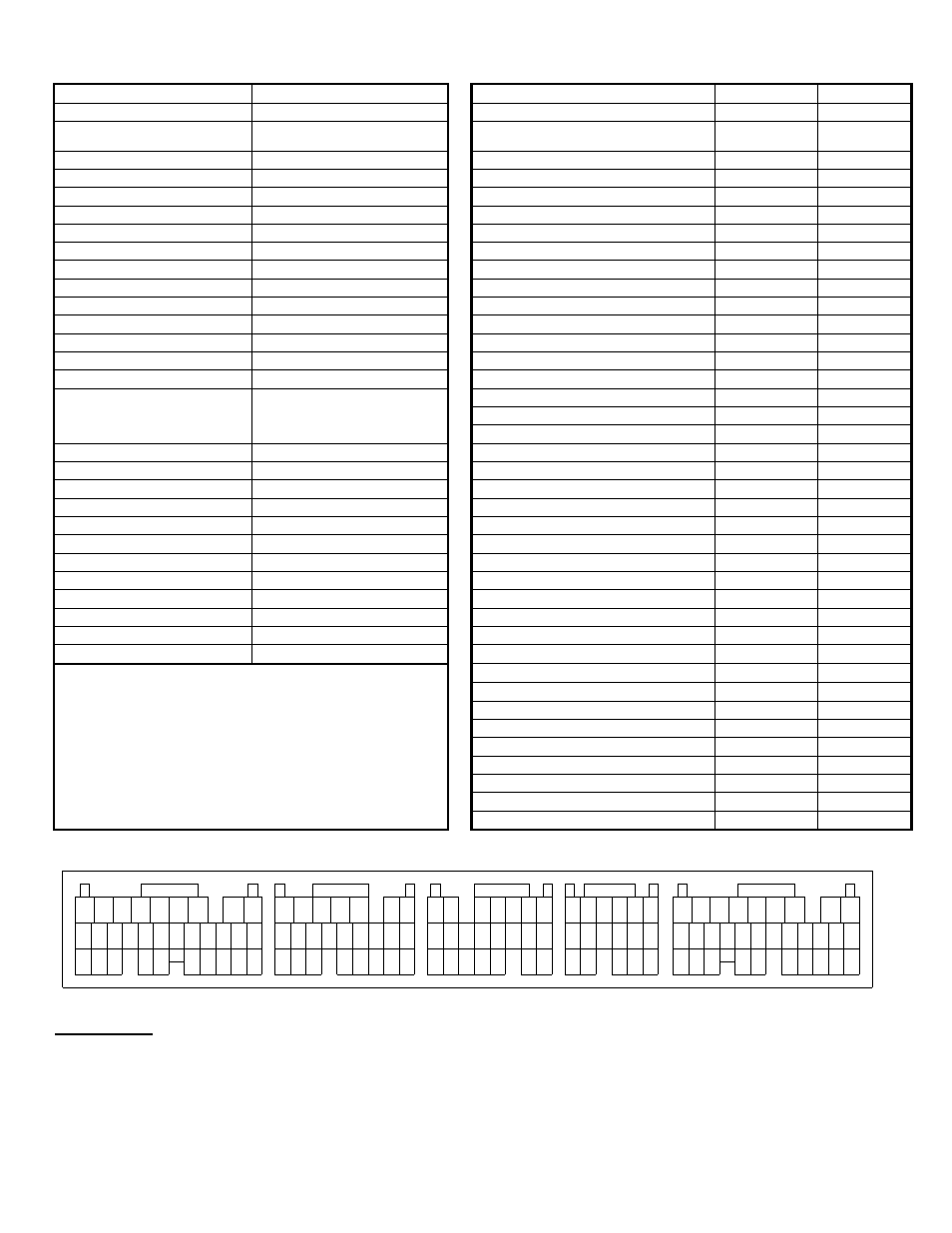
Wire view of aem ems, Subaru impreza wrx sti (usdm 2.5l), Connector a – AEM 30-6821 Series 2 Plug & Play EMS User Manual
Page 16: Connector b, Connector c, Connector d, Connector e
Page 16 of 21
Application Notes for EMS P/N 30-6820 / 30-6821
Subaru Impreza WRX STI (USDM 2.5L)
Make:
Subaru
Description
Function
ECU Pin #
Model:
Impreza WRX STI
Spare Injector Driver (max 1.5A):
Injector 5
C2
Years Covered:
2004 (30-6820 EMS)
2005-2006 (30-6821 EMS)
Spare Injector Driver (max 1.5A):
Injector 6
C1
Engine Displacement:
2.5L
Spare Injector Driver (max 1.5A):
Injector 7
A6
Engine Configuration:
Flat 4
Spare Injector Driver (max 1.5A):
Injector 8
A7
Firing Order:
1-3-2-4
Spare Coil Driver (0-5V falling edge):
Coil 5
B13
N/A, S/C or T/C:
Turbocharged
Spare Coil Driver (0-5V falling edge):
Coil 6
B14
MAP Min:
0.8V @ -14.7 PSIg
Boost Solenoid:
PW 2
A32
MAP Max:
4.59V @ 23.8 PSIg
EGT 1 Location:
EGT 1
C12
# Coils:
4, with internal igniters
EGT 2 Location:
EGT 2
D20
Ignition driver type:
0-5V, Falling Edge trigger
EGT 3 Location:
EGT 3
D24
# of Injectors:
4 (Inj 1-4)
EGT 4 Location:
EGT 4
D29
Factory Injectors:
500 cc/min saturated
Spare 0-5V Input Channel:
ADCR 13
A33
Factory Inj Resistors:
No
Spare 0-5V Input Channel:
ADCR 11
C27
Injection Mode:
Sequential
Spare 0-5V Input Channel:
ADCR 14
C26
Knock Sensors used:
1 (Knock 1)
Spare Low Side Output Driver:
Low side 2
A13
Lambda Sensors used:
2 (aftermarket wideband sensor
required, OEM O2 sensors not
supported)
Spare Low Side Output Driver:
Low side 3
A12
Spare Low Side Output Driver:
Low side 4
A14
Spare Low Side Output Driver:
Low side 11
A24
Idle Motor Type:
None (Electronic Throttle)
Spare Low Side Output Driver:
Main Relay Control:
Yes (Switch 1 in, Coil7 output)
Spare Low Side Output Driver:
Crank Pickup Type:
Magnetic
Spare Low Side Output Driver:
Crank Teeth/Cycle:
36-2-2-2
Spare Low Side Output Driver:
Cam Pickup Type:
Hall Effect
Spare Low Side Output Driver:
Cam Teeth/Cycle:
3
Spare Low Side Output Driver:
Transmissions Offered:
Manual
Spare Low Side Output Driver:
Trans Supported:
Manual
Check Engine Light:
Low side 10
A17
Drive Options:
AWD
Spare High Side Driver:
High side 1
B34
Supplied Connectors:
---
Spare High Side Driver:
AEM Extension/patch harness
30-2988
Spare High Side Driver:
AEM Plug/pin kit:
N/A
Spare High Side Driver:
Spare High Side Driver:
Spare High Side Driver:
VVC Low Side Driver (RH cam):
Injector 9
A28
VVC Low Side Driver (LH cam):
Injector 10
A29
Spare Switch Input (switch to GND):
Switch 2*
C9
Spare Switch Input: (switch to +12V)
Switch 3**
A1
Spare Switch Input (switch to GND):
Switch 4*
D11
Spare Switch Input (switch to GND):
Switch 5*
D13
Spare Switch Input (switch to +12V):
Switch 6**
D16 / D17
Wire View of AEM EMS
22
10
7 8 9
11 12
10
10
12 13 14 15
11
9
8
16
15
14
13
12
11
10
8 9
21
20
19
18
17
16
15
14
13
12
11
10
Connector A
27
23
22
24
26
25
16
19
Connector B
31
29
28
30
17 18
22
20 21
24
23
20
Connector C
18
17
19
21 22
15
Connector D
14
13
17
16
1
2
3
5
4
6
1
9
7
8
1
2
4
3
5
6 7
2
3 4 5
6 7
1 2 3 4 5 6
21
19
18
17
16
15
14
13
12
20
11
Connector E
25
24
23
26
27
31
28 29 30
7
4
1
2
3
5
6
8
9
WARNING:
*Switch input pins Switch 2, Switch4, Switch5 must connect to ground; the switch should not
provide 12V power to the EMS because that will not be detected as on or off.
**Switch input pins Switch 3, Switch6, must connect to +12V; the switch should not provide GND to
the EMS because that will not be detected as on or off.