AEM 30-6611 Series 2 Plug & Play EMS User Manual
Page 4
Page 4 of 13
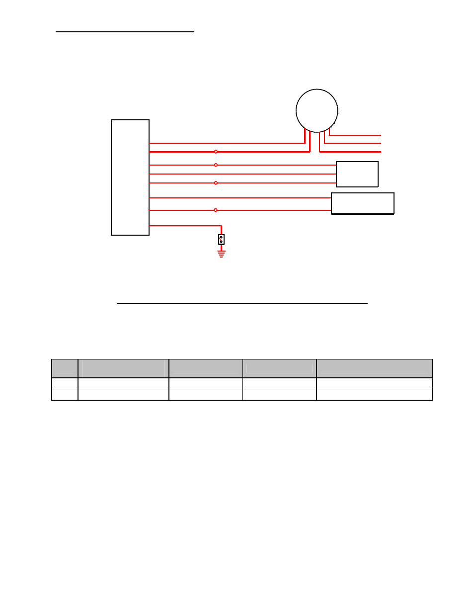
Wiring accessories to the EMS:
Please follow this suggested wiring diagram when adding accessories such as UEGO
gauges, MAP sensors, IAT sensors, or switches for use with the EMS. Note that wire
polarity is not important for the Air Temperature sensor.
35
50
63
AEM EMS
P/N: 30-6611
66
50
49
46
50
Switched Input
Ground
Switch 1
Sensor Ground (tapped)
Air Temperature Sensor
P/N: 30-2010
IAT Sensor
O2 Sensor 1
+5V Sensor Power (tapped)
Sensor Ground (tapped)
MAP Signal
Sensor Ground (tapped)
MAP Sensor
P/N: 30-2130-50
Black (Battery or chassis ground)
Red (+12V power, 5A fuse)
Pink (Switched +12V Power)
White (0-5V Analog + signal)
Brown (Analog - signal)
Black (Sensor Ground)
Green (MAP Signal)
Red (+5V Sensor Power)
AEM UEGO
P/N: 30-5130
30-1611 (Series 1) vs 30-6611 (Series 2) EMS differences:
The EMS functions assigned to certain pins have been changed and no longer match the
30-1611 EMS. Unless otherwise noted, the following pins and functions will need to be
manually reconfigured after using AEMTuner to convert a V1.19 30-1611, Series 1 EMS
calibration for use with the 30-6611 Series 2 hardware.
Pin
Vehicle harness
destination
30-1611 function
30-6611 function
Notes
12
A/C triple press sw
---
CAN1L
Changed to CAN low side
69
---
Coil #5
CAN1H
Changed to CAN high side