Wire view of aem ems – AEM 30-6611 Series 2 Plug & Play EMS User Manual
Page 10
Page 10 of 13
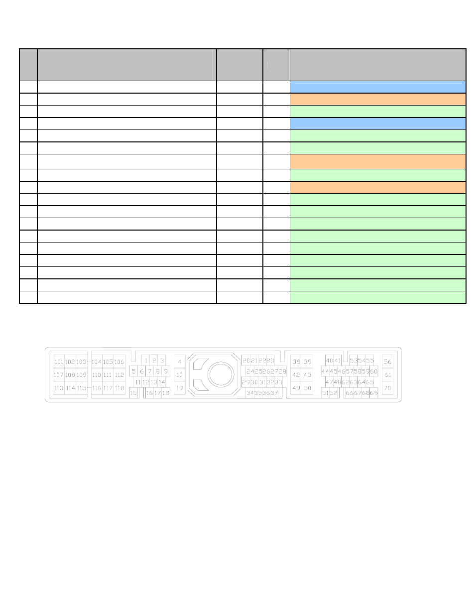
Connection Diagram for EMS P/N 30-6611
Pin
1996-1998 Nissan 240SX S14 KA24DE (OBDII)
1997-1999 Nissan Sentra B14 SR20DE & GA16DE (Except 97 2.0L)
1997-1998 Nissan 200SX B14 SR20DE & GA16DE (Except 97 2.0L)
1996-1999 Nissan Altima U13 KA24DE
(Except 96 Non CA models)
1999 Infiniti G20 P10 SR20DE
AEM EMS
30-6611
I/O
Notes
20
Start Signal
Start
Input
Dedicated, start signal
21
Air Conditioner Switch
Switch 6
Input
PnP for air conditioning switch
22
M/T Neutral Position Switch
Switch 4
Input
Available, switched input
23
Throttle Position Sensor
TPS
Input
Dedicated, throttle position sensor
24
Blower Fan Switch (97-99 1.6L Only)
ADCR13
Input
Available, 0-5V input
25
Power Steering Oil Pressure Switch
Switch 2
Input
Available, switched input
26
Vehicle Speed Sensor
Vehicle
Speed (T3)
Input
PnP for vehicle speed
27
Throttle Closed Switch
Switch 5
Input
Available, switched input
28
Intake Air Temperature Sensor
IAT
Input
PnP for intake air temperature
29
A/T Signal 2
Injector 5
Output
Available, switched ground, 1.5A max
30
A/T Signal 3
Injector 6
Output
Available, switched ground, 1.5A max
31
--- Injector
7
Output
Available, switched ground, 1.5A max
32
--- Injector
8
Output
Available, switched ground, 1.5A max
33
A/T Signal 4 (Throttle Position Signal)
Idle 6
Output
Available, switched ground, 1.5A max
34
--- PW
2
Output
Available, pulse width out
35
--- Switch
1
Input
Available, switched input
36
--- Coil
4
Output
Available, coil 4, 0-5V falling edge trigger
37
---
Low Side 2
Output
Available, switched ground, 1.5A max (connected to Pin 57)
Wire View of AEM EMS