AEM 30-3520 Infinity Plug & Play Harnesses - Nissan/Infiniti 2003-2006 350Z/G35 User Manual
Page 28
28
© 2014 AEM Performance Electronics
P/N 30-3520
Infinity
Pin
Hardware Reference
2003–2006 350Z/
G35
Specification
Dest. Pin
350Z/
G35
Hardware Specification
Notes
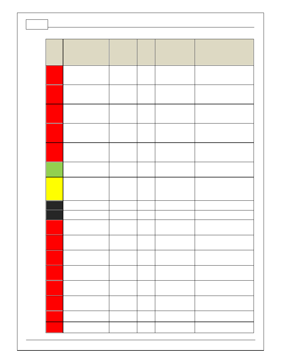
C1-12
Harness_Coil_2
Coil 3
61
25 mA max source
current
0–5V Falling edge f ire. DO NOT
connect directly to coil primary . Must
use an ignitor OR CDI that accepts a
FALLING edge f ire signal.
C1-13
Harness_Coil_1
Coil 2
81
25 mA max source
current
0–5V Falling edge f ire. DO NOT
connect directly to coil primary . Must
use an ignitor OR CDI that accepts a
FALLING edge f ire signal.
C1-14
Harness_Coil_0
Coil 1
62
25 mA max source
current
0–5V Falling edge f ire. DO NOT
connect directly to coil primary . Must
use an ignitor OR CDI that accepts a
FALLING edge f ire signal.
C1-15
Harness_Coil_5
Coil 6
79
25 mA max source
current
0–5V Falling edge f ire. DO NOT
connect directly to coil primary . Must
use an ignitor OR CDI that accepts a
FALLING edge f ire signal.
C1-16
Harness_Coil_4
Coil 5
60
25 mA max source
current
0–5V Falling edge f ire. DO NOT
connect directly to coil primary . Must
use an ignitor OR CDI that accepts a
FALLING edge f ire signal.
C1-17
Harness_LowsideSwitch_2
Rad Fan 1
NC
Lowside switch, 1.7A
max, NO internal f ly back
diode.
See Setup Wizard Page LowSide
Assignment Tables f or activ ation
criteria.
C1-18
Harness_LowsideSwitch_3
VVC1A
11
Lowside switch, 6A max
with internal f ly back
diode. Inductiv e load
should NOT hav e f ull
time power.
See Setup Wizard Page LowSide
Assignment Tables f or activ ation
criteria.
C1-19
AGND_1
Sensor Ground
66
Dedicated analog ground
Analog 0–5V sensor ground
C1-20
AGND_1
Sensor Ground
67
Dedicated analog ground
Analog 0–5V sensor ground
C1-21
Harness_Digital_In_0
Crankshaf t
Position Sensor
Hall
13
10K pullup to 12V. Will
work with ground or
f loating switches.
See Setup Wizard page Cam/Crank
f or options.
C1-22
Harness_Digital_In_1
Camshaf t
Position Sensor
1 Hall
33
10K pullup to 12V. Will
work with ground or
f loating switches.
See Setup Wizard page Cam/Crank
f or options.
C1-23
Harness_Digital_In_2
Camshaf t
Position Sensor
2 Hall
14
10K pullup to 12V. Will
work with ground or
f loating switches.
See Setup Wizard page Cam/Crank
f or options.
C1-24
Harness_Digital_In_3
Camshaf t
Position Sensor
4 Hall
72
10K pullup to 12V. Will
work with ground or
f loating switches.
See Setup Wizard page Cam/Crank
f or options.
C1-25
Harness_Digital_In_4
Camshaf t
Position Sensor
3 Hall
53
10K pullup to 12V. Will
work with ground or
f loating switches.
See Setup Wizard page Cam/Crank
f or options.
C1-26
Harness_Digital_In_5
Flex Fuel
10K pullup to 12V. Will
work with ground or
f loating switches.
See channel FlexDigitalIn [Hz] f or raw
f requency input data.
C1-27
Harness_Knock_In_0
Knock Sensor 1
15
Dedicated knock signal
processor
See Setup Wizard page Knock Setup
f or options.
C1-28
Harness_Knock_In_1
Knock Sensor 2
NC
Dedicated knock signal
processor
See Setup Wizard page Knock Setup
f or options.