Infinity pinouts – AEM 30-3520 Infinity Plug & Play Harnesses - Nissan/Infiniti 2003-2006 350Z/G35 User Manual
Page 27
2003–2006 Nissan 350Z/Infiniti G35
27
© 2014 AEM Performance Electronics
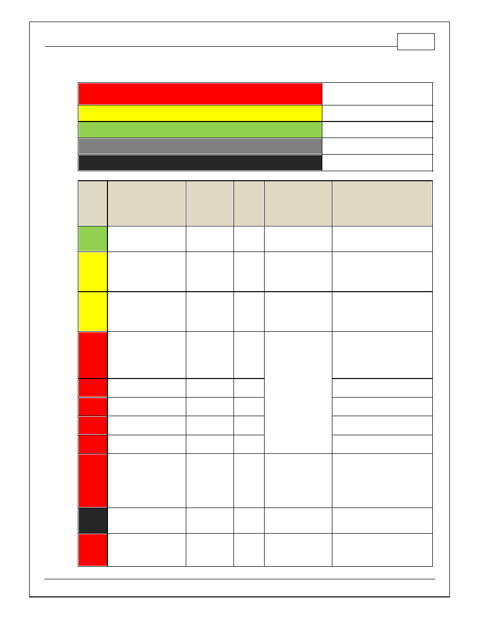
Infinity Pinouts
Dedicated
Dedicated and not
reconfigurable
Assigned
Assigned but reconfigurable
Available
Available for user setup
Not Applicable
Not used in this configuration
Required
Required for proper function
Infinity
Pin
Hardware Reference
2003–2006 350Z/
G35
Specification
Dest. Pin
350Z/
G35
Hardware Specification
Notes
C1-1
Harness_LowsideSwitch_4
A/C Compressor
Clutch Relay
Lowside switch, 1.7A
max, NO internal f ly back
diode.
See Setup Wizard Page LowSide
Assignment Tables f or activ ation
criteria.
C1-2
Harness_LowsideSwitch_6
VVC2A Solenoid
Control
9
Lowside switch, 6A max
with internal f ly back
diode. Inductiv e load
should NOT hav e f ull
time power.
See Setup Wizard Page LowSide
Assignment Tables f or activ ation
criteria.
C1-3
Harness_LowsideSwitch_5
VVC1B Solenoid
Control
10
Lowside switch, 6A max
with internal f ly back
diode. Inductiv e load
should NOT hav e f ull
time power.
See Setup Wizard Page LowSide
Assignment Tables f or activ ation
criteria.
C1-4
Harness_UEGO_Heat-_1
UEGO 1 Heat
2
Bosch UEGO controller
Lowside switch f or UEGO heater
control. Connect to pin 4 of Bosch
UEGO sensor. NOTE that pin 3 of the
Sensor is heater (+) and must be
power by a f used/switched 12V
supply .
C1-5
Harness_UEGO_IA_1
UEGO 1 IA
75
Trim Current signal. Connect to pin 2
of Bosch UEGO sensor.
C1-6
Harness_UEGO_IP_1
UEGO 1 IP
56
Pumping Current signal. Connect to
pin 6 of Bosch UEGO sensor.
C1-7
Harness_UEGO_UN_1
UEGO 1 UN
16
Nernst Voltage signal. Connect to pin
1 of Bosch UEGO sensor.
C1-8
Harness_UEGO_VM_1
UEGO 1 VM
35
Virtual Ground signal. Connect to pin 5
of Bosch UEGO sensor.
C1-9
Harness_Flash_Enable
Harness Flash
Enable
10K pulldown
Not usually needed f or automatic
f irmware updates through Inf inity
Tuner. If connection errors occur
during update, connect 12 v olts to this
pin bef ore proceeding with upgrade.
Disconnect the 12 v olts signal af ter
the update.
C1-10
+12V_R8C_CPU
Battery Perm
Power
121
Dedicated power
management CPU
Full time battery power. MUST be
powered bef ore the ignition switch
input is triggered (See C1-65).
C1-11
Harness_Coil_3
Coil 4
80
25 mA max source
current
0–5V Falling edge f ire. DO NOT
connect directly to coil primary . Must
use an ignitor OR CDI that accepts a
FALLING edge f ire signal.