Aux connector pinouts – AEM 30-3510 Infinity Plug & Play Harnesses - BMW 2001-2006 E46 M3 User Manual
Page 39
2001–2006 BMW E46 M3
39
© 2014 AEM Performance Electronics
Infinity
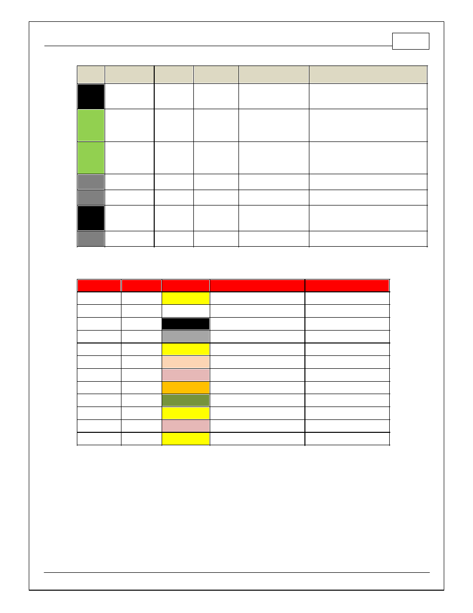
Pin
Hardware
Reference
AEM / M3
Function
BMW M3
Pin
Hardware Specification
Notes
C2-50
+12V_R8C_CPU
Battery Perm
Power
Dedicated power
management CPU
Optional f ull time battery power. MUST be
powered bef ore the ignition switch input is
triggered. (See C1-65.)
C2-51
Coil 7
Coil 7
25 mA max source current
0-5V Falling edge f ire. DO NOT connect
directly to coil primary . Must use an ignitor
OR CDI that accepts a FALLING edge f ire
signal.
C2-52
Coil 8
Coil 8
25 mA max source current
0-5V Falling edge f ire. DO NOT connect
directly to coil primary . Must use an ignitor
OR CDI that accepts a FALLING edge f ire
signal.
C2-53
Coil 9
Coil 9
25 mA max source current
Not Av ailable
C2-54
Coil 10
Coil 10
25 mA max source current
Not Av ailable
C2-55
HighsideSwitch_2
Fuel Pump
Multi-f unction pin
depending on hardware
conf iguration
+12V High Side Driv e. Will prime f or 2
seconds at key on and activ ate if RPM > 0.
C2-56
Not used
Not used
Not used
Not used
AUX Connector Pinouts
Deutsch Pin
Infinity Pin
Wire Color
Pin Nam e
Default Pin Function
1
C1-37
Yellow
Harness_Analog_In_9
Fuel Press
2
C1-67
White
Harness_Analog_In_Temp_2
Intake Air Temp
3
C1-19
Black
AGND_2
Sensor Ground
4
C1-41
Gray
+5V_OUT_1
Sensor +5V
5
C1-36
Yellow
Harness_Analog_In_8
Manifold Pressure
6
C1-26
Tan
Harness_Digital_In_5
Flex Fuel Sensor (Hz)
7
C1-33
Pink
Harness_Low sideSw itch_1
Boost Control
8
C1-64
Orange
+12V
+12V
9
C1-44
Dark Green
Harness_HighsideSw itch_0
HS0
10
C1-40
Yellow
Harness_Analog_In_12
Boost Sw itch
11
C1-17
Pink
Harness_Low sideSw itch_2
Rad Fan1
12
C1-39
Yellow
Harness_Analog_In_11
No Lift Shift Trigger