AEM 30-3510 Infinity Plug & Play Harnesses - BMW 2001-2006 E46 M3 User Manual
Page 36
36
© 2014 AEM Performance Electronics
P/N 30-3510
Infinity
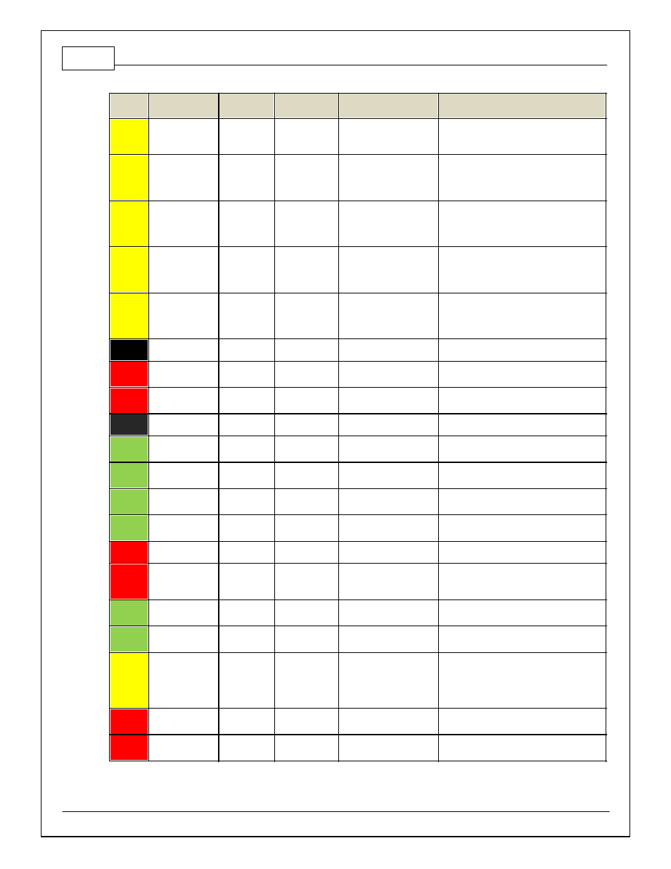
Pin
Hardware
Reference
AEM / M3
Function
BMW M3
Pin
Hardware Specification
Notes
C1-68
Harness_Analog_I
n_Temp_3
Oil
Temperature
Sensor
12 bit A/D, 2.49K pullup to
5V
See 1D table OilTempCal table f or calibration
data and OilTemp [C] f or channel data.
C1-69
Stepper_2A
Stepper 2A
Automotiv e,
Programmable Stepper
Driv er, up to 28V and
±1.4A
Be sure that each internal coil of the stepper
motor is properly paired with the 1A/1B and
2A/2B ECU outputs. Supports Bi-Polar
stepper motors only .
C1-70
Stepper_1A
Stepper 1A
Automotiv e,
Programmable Stepper
Driv er, up to 28V and
±1.4A
Be sure that each internal coil of the stepper
motor is properly paired with the 1A/1B and
2A/2B ECU outputs. Supports Bi-Polar stepper
motors only .
C1-71
Stepper_2B
Stepper 2B
Automotiv e,
Programmable Stepper
Driv er, up to 28V and
±1.4A
Be sure that each internal coil of the stepper
motor is properly paired with the 1A/1B and
2A/2B ECU outputs. Supports Bi-Polar stepper
motors only .
C1-72
Stepper_1B
Stepper 1B
Automotiv e,
Programmable Stepper
Driv er, up to 28V and
±1.4A
Be sure that each internal coil of the stepper
motor is properly paired with the 1A/1B and
2A/2B ECU outputs. Supports Bi-Polar stepper
motors only .
C1-73
Power Ground
Ground
5-5
Power Ground
Connect directly to ground.
C2-1
DBW2 Motor +
DBW Motor
Control Open
5.0A max Throttle Control
Hbridge Driv e
+12V to open
C2-2
DBW2 Motor -
DBW Motor
Control Close
5.0A max Throttle Control
Hbridge Driv e
+12V to close
C2-3
Power Ground
Ground
4-5
Power Ground
Connect directly to ground.
C2-4
Injector 7
Injector 7
Saturated or peak and
hold, 3A max continuous
Injector 7
C2-5
Injector 8
Injector 8
Saturated or peak and
hold, 3A max continuous
Injector 8
C2-6
Injector 9
Injector 9
Saturated or peak and
hold, 3A max continuous
NOTE: Only av ailable with Inf inity 10 BMW, P/
N: 30-7105
C2-7
Injector 10
Injector 10
Saturated or peak and
hold, 3A max continuous
NOTE: Only av ailable with Inf inity 10 BMW, P/
N: 30-7105
C2-8
Power Ground
Ground
Power Ground
Connect directly to battery ground.
C2-9
+12V
+12V In
12 v olt power f rom relay
12 v olt power f rom relay . Relay must be
controlled by +12V Relay Control signal, pin
C1-29 abov e.
C2-10
Injector 11
Injector 11
Saturated or peak and
hold, 3A max continuous
NOTE: Only av ailable with Inf inity 10 BMW, P/
N: 30-7105
C2-11
Injector 12
Injector 12
Saturated or peak and
hold, 3A max continuous
NOTE: Only av ailable with Inf inity 10 BMW, P/
N: 30-7105
C2-12
Analog_In_17
A/C Analog
Request
12 bit A/D, 100K pullup to
5V
0–5V analog signal. Use +5V Out pins as
power supply and Sensor Ground pins as the
low ref erence. See Setup Wizard Input
Functions page f or input selection. BMW uses
CAN bus f or A/C switch input
C2-13
Analog_In_18
DBW_APP1
[%]
4-8
12 bit A/D, 100K pullup to
5V
0–5V analog signal.
C2-14
Analog_In_19
DBW_APP2
[%]
4-13
12 bit A/D, 100K pullup to
5V
0–5V analog signal.