AEM 30-3510 Infinity Plug & Play Harnesses - BMW 2001-2006 E46 M3 User Manual
Page 38
38
© 2014 AEM Performance Electronics
P/N 30-3510
Infinity
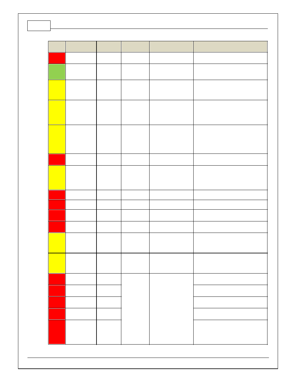
Pin
Hardware
Reference
AEM / M3
Function
BMW M3
Pin
Hardware Specification
Notes
C2-32
AGND_2
MAF Sensor
Ground
3-17
Dedicated analog ground
Analog 0–5V sensor ground
C2-33
Analog_In_20
MAF Sensor
Signal
3-1
12 bit A/D, 100K pullup to
5V
0–5V analog signal. Use +5V Out pins as
power supply and Sensor Ground pins as the
low ref erence.
C2-34
Analog_In_21
3 Step Enable
Switch
12 bit A/D, 100K pullup to
5V
0–5V analog signal. Use +5V Out pins as
power supply and Sensor Ground pins as the
low ref erence. See 3StepSwitch 1-axis table
f or setup.
C2-35
Analog_In_22
USB Logging
Activ ate
12 bit A/D, 100K pullup to
5V
0–5V analog signal. Use +5V Out pins as
power supply and Sensor Ground pins as the
low ref erence. See USBLoggingRequestIn
channel f or input state. See Setup Wizard
page USB Logging f or conf iguration options.
C2-36
Analog_In_23
Charge Out
Pressure
12 bit A/D, 100K pullup to
5V
0–5V analog signal. Use +5V Out pins as
power supply and Sensor Ground pins as the
low ref erence. See ChargeOutPress [kPa]
channel f or input state. See Setup Wizard
page Charge Out Pressure f or calibration
options.
C2-37
Digital_In_6
Brake Switch
Input
4-24
No pullup. Will work with
TTL signals.
Input used f or CAN bus
C2-38
Digital_In_7
Gear
Recognition
Clutch Switch
2-20
No pullup. Will work with
TTL signals.
Circuit is open unless clutch is out and gear
in. See ClutchSwitch 1-axis table f or setup
options. Input can be assigned to dif f erent
pins. See Setup Wizard page Input Function
Assignments f or input mapping options.
C2-39
Power Ground
Ground
Power Ground
Connect directly to battery ground.
C2-40
Power Ground
Ground
Power Ground
Connect directly to battery ground.
C2-41
CanH_Bout
CANH
4-36
Dedicated High Speed
CAN Transceiv er
Used f or BMW CAN bus
C2-42
CanL_Bout
CANL
4-37
Dedicated High Speed
CAN Transceiv er
Used f or BMW CAN bus
C2-43
LowsideSwitch_8
A/C Fan
4-4
Lowside switch, 4A max
with internal f ly back diode.
Inductiv e load should NOT
hav e f ull time power.
See Setup Wizard Page "LowSide Assignment
Tables" f or output assignment and 2D table
"LS8_Duty [%]" f or activ ation.
C2-44
LowsideSwitch_7
Vanos- Intake
Cam
3-4, 3-50
Lowside switch, 4A max
with internal f ly back diode.
Inductiv e load should NOT
hav e f ull time power.
See Setup Wizard Page "LowSide Assignment
Tables" f or output assignment and 2D table
"LS7_Duty [%]" f or activ ation.
C2-45
UEGO 2 VM
UEGO 2 VM
Bosch UEGO Controller
Virtual Ground signal. Connect to pin 5 of
Bosch UEGO sensor.
C2-46
UEGO 2 UN
UEGO 2 UN
Nernst Voltage signal. Connect to pin 1 of
Bosch UEGO sensor.
C2-47
UEGO 2 IP
UEGO 2 IP
Pumping Current signal. Connect to pin 6 of
Bosch UEGO sensor.
C2-48
UEGO 2 IA
UEGO 2 IA
Trim Current signal. Connect to pin 2 of Bosch
UEGO sensor.
C2-49
UEGO 2 HEAT
UEGO 2
HEAT
Lowside switch f or UEGO heater control.
Connect to pin 4 of Bosch UEGO sensor.
NOTE that pin 3 of the Sensor is heater (+)
and must be power by a f used/switched 12V
supply .