Infinity pinouts – AEM 30-3510 Infinity Plug & Play Harnesses - BMW 2001-2006 E46 M3 User Manual
Page 32
32
© 2014 AEM Performance Electronics
P/N 30-3510
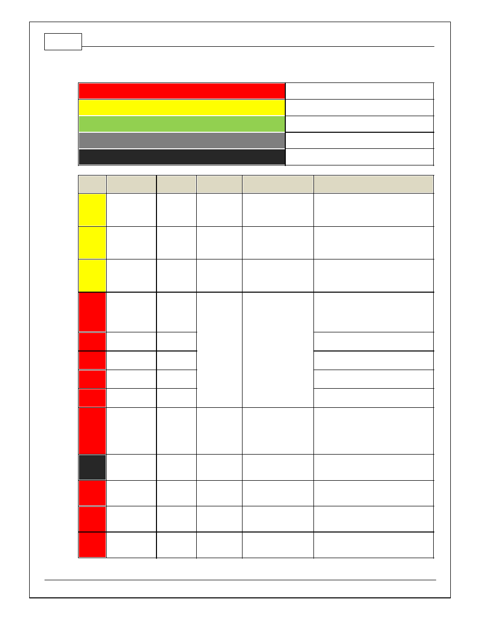
Infinity Pinouts
Dedicated
Dedicated and not reconfigurable
Assigned
Assigned but reconfigurable
Available
Available for user setup
Not Applicable
Not used in this configuration
Required
Required for proper function
Infinity
Pin
Hardware
Reference
AEM / M3
Function
BMW M3
Pin
Hardware Specification
Notes
C1-1
LowsideSwitch_4
A/C
Compressor
Clutch Relay
4-29
Lowside switch, 4A max,
NO internal f ly back diode.
See Setup Wizard Page "LowSide Assignment
Tables" f or output assignment, Honda VTEC
f or VANOS triggering and 2D table "LS3_Duty
[%]" f or on/of f activ ation.
C1-2
LowsideSwitch_5
Vanos-
Exhaust Cam
3-43, 3-44
Lowside switch, 4A max
with internal f ly back diode.
Inductiv e load should NOT
hav e f ull time power.
The Vanos driv ers are located in the AEM
Jumper Box. BMW Vanos cannot be wired
directly to the Inf inity .
C1-3
LowsideSwitch_6
Idle Air
Control
3-46, 3-47
Lowside switch, 4A max
with internal f ly back diode.
Inductiv e load should NOT
hav e f ull time power.
The S54 engine uses both an IACV and driv e
by wire throttles. Idle speed and low APP
request is controlled using the IACV.
C1-4
UEGO 1 Heat
UEGO 1 Heat
Use 30-3600
Inf inity O2
Sensor
Extension
Harness
Bosch UEGO controller
Lowside switch f or UEGO heater control.
Connect to pin 4 of Bosch UEGO sensor.
NOTE that pin 3 of the Sensor is heater (+)
and must be power by a f used/switched 12V
supply .
C1-5
UEGO 1 IA
UEGO 1 IA
Trim Current signal. Connect to pin 2 of Bosch
UEGO sensor.
C1-6
UEGO 1 IP
UEGO 1 IP
Pumping Current signal. Connect to pin 6 of
Bosch UEGO sensor.
C1-7
UEGO 1 UN
UEGO 1 UN
Nernst Voltage signal. Connect to pin 1 of
Bosch UEGO sensor.
C1-8
UEGO 1 VM
UEGO 1 VM
Virtual Ground signal. Connect to pin 5 of
Bosch UEGO sensor.
C1-9
Flash_Enable
Flash Enable
10K pulldown
Not usually needed f or automatic f irmware
updates through Inf inity Tuner. If connection
errors occur during update, jump the 12V
Flash Connector bef ore proceeding with
upgrade. Disconnect the 12V Flash Connector
af ter the update.
C1-10
+12V_R8C_CPU
Battery Perm
12V Power
1-7
Dedicated power
management CPU
Full time battery power. MUST be powered
bef ore the ignition switch input is triggered.
(See C1-65.)
C1-11
Coil 4
Coil 4
5-9
25 mA max source current
The ignitors are f ound in the AEM Jumper Box.
The BMW Coils cannot be wired directly to the
Inf inity .
C1-12
Coil 3
Coil 3
5-3
25 mA max source current
The ignitors are f ound in the AEM Jumper Box.
The BMW Coils cannot be wired directly to the
Inf inity .
C1-13
Coil 2
Coil 2
5-2
25 mA max source current
The ignitors are f ound in the AEM Jumper Box.
The BMW Coils cannot be wired directly to the
Inf inity .