Bryant R-410A 583B User Manual
Page 15
MEASURE MANIFOLD PRESSURE (Propane Units)—The
main burner orifices on a propane unit are sized for the unit rated
input when the manifold pressure reading matches the level
specified in Table 6.
WARNING: If converting to propane gas, remove the
burner assembly and inspect the heat exchanger tubes. If
there are V-shaped NOx baffles installed in the firing
tubes, THEY MUST BE REMOVED.
Discard the baffles after removal.
Refer to Maintenance section for information on burner
removal.
Proceed as follows to adjust gas input on a propane gas unit:
1. Turn off gas to unit.
2. Remove pipe plug on manifold (see Fig. 16) then connect
manometer at this point.
3. Turn on gas to unit.
4. Remove cover screw over regulator adjustment screw on
gas valve.
5. Adjust regulator adjustment screw to the correct manifold
pressure, as specified in Table 6. Turn adjusting screw
clockwise to increase manifold pressure, or turn adjusting
screw counterclockwise to decrease manifold pressure.
6. Replace cover screw.
7. Turn off gas to unit. Remove manometer from pressure tap.
Replace pipe plug on gas valve, then turn on gas to unit.
check for leaks.
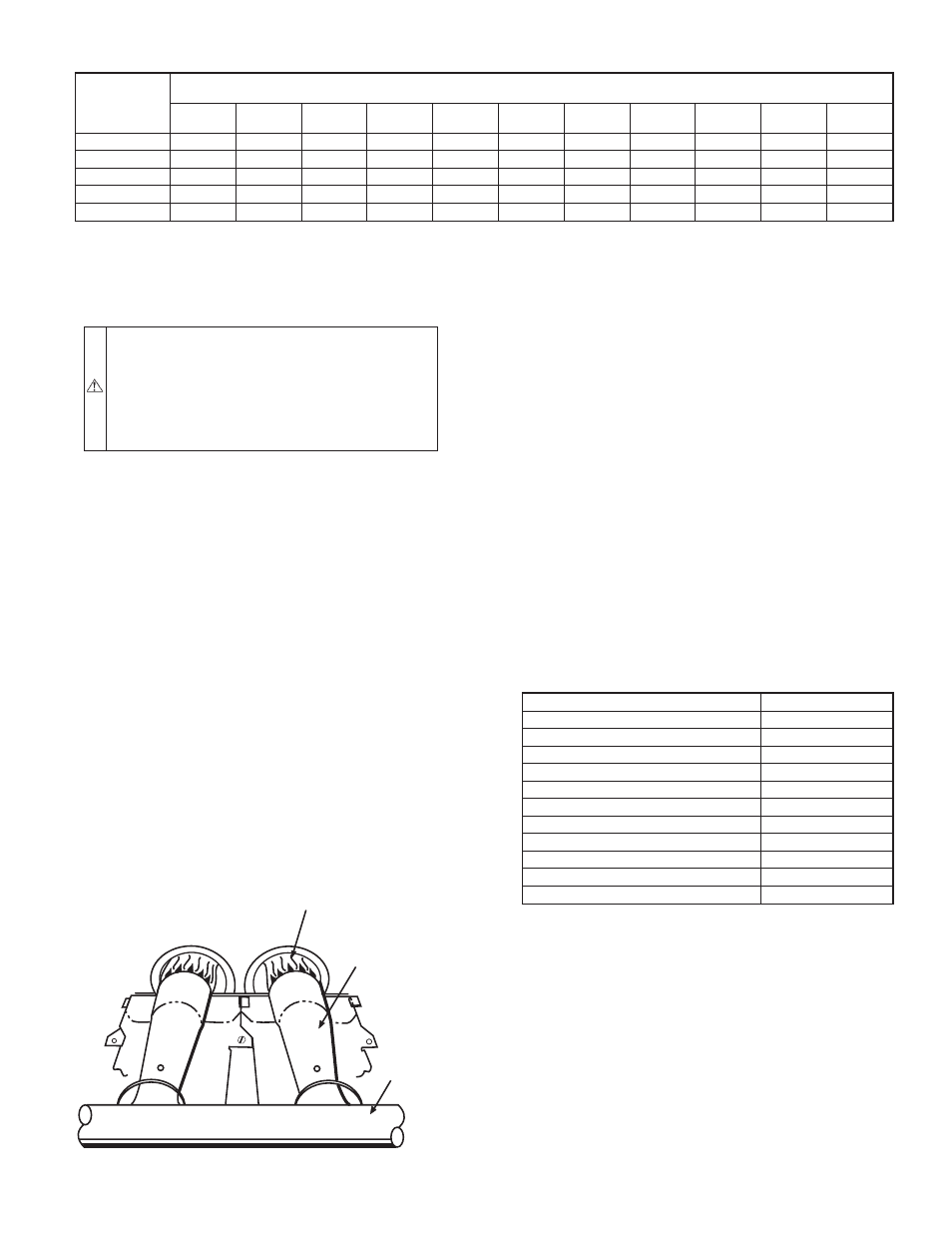
CHECK BURNER FLAME—With burner access panel removed,
observe the unit heating operation. Watch the burner flames to see
if they are light blue and soft in appearance, and that the flames are
approximately the same for each burner. Propane will have blue
flame with yellow tips. (See Fig. 17). Refer to Maintenance section
for information on burner removal.
AIRFLOW AND TEMPERATURE RISE—The heating section
for each size unit is designed and approved for heating operation
within the temperature rise range stamped on the unit rating plate.
Table 7 shows the approved temperature rise range for each
heating input, and the air delivery cfm at various temperature rises.
The heating operation airflow must produce a temperature rise that
falls within the approved range.
Refer to Indoor Airflow and Airflow Adjustments section on the
following pages to adjust heating airflow when required.
HEATING SEQUENCE OF OPERATION—See Fig. 18-19 and
unit wiring label.
On a call for heating, terminal "W" of the thermostat is energized,
starting the induced-draft motor. When the hall-effect sensor on
the induced-draft motor senses that it has reached the required
speed, the burner sequence begins. This function is performed by
the integrated gas control (IGC). The evaporator fan motor is
energized 45 seconds after flame is established. When the thermo-
stat is satisfied and "W" is de-energized, the burners stop firing and
the evaporator fan motor shuts off after a 45-second time-off delay.
An LED (light-emitting diode) indicator is provided on the control
board to monitor operation. The control board is located by
removing the burner access panel. During normal operation, the
LED is continuously on. See Table 8 for error codes.
TABLE 8—LED INDICATIONS
ERROR CODE
LED INDICATION
Normal Operation
On
Hardware Failure
Off
Fan On/Off Delay Modified
1 Flash
Limit Switch Fault
2 Flashes
Flame Sense Fault
3 Flashes
Four Consecutive Limit Switch Faults
4 Flashes
Ignition Lockout Fault
5 Flashes
Induced-Draft Motor Fault
6 Flashes
Rollout Switch Fault
7 Flashes
Internal Control Fault
8 Flashes
Internal Software Fault
9 Flashes
NOTES:
1.There is a 3-second pause between error code displays.
2. If more than one error code exists, all applicable error codes will be
displayed in numerical sequence.
3. This chart is on the wiring diagram located inside the burner access
panel.
LIMIT SWITCHES—Normally closed limit switch (LS) com-
pletes the control circuit through the thermostat R circuit. Should
the leaving-air temperature rise above the maximum allowable
temperature, the limit switch opens and the R control circuit
"breaks". Any interruption in the R control circuit instantly closes
the gas valve and stops gas flow to the burners and pilot. The
blower motor continues to run until LS resets.
When the air temperature at the limit switch drops to the
low-temperature setting of the limit switch, the switch closes and
completes the R control circuit. The electric spark ignition system
cycles and the unit returns to normal heating operation. When this
fault occurs, the IGC LED will display FAULT CODE 2.
TABLE 7—AIR DELIVERY (CFM) AT INDICATED TEMPERATURE RISE AND RATED HEATING INPUT
HEATING
INPUT
(BTUH)
INPUT
TEMPERATURE RISE °F
20
25
30
35
40
45
50
55
60
65
70
40,000
1500
1200
1000
857
750
667
600
—
—
—
—
60,000
2250
1800
1500
1286
1125
1000
900
818
750
692
—
90,000
—
2700
2250
1929
1688
1500
1350
1227
1125
1038
964
115,000
—
—
—
2464
2156
1917
1725
1568
1438
1327
—
130,000
—
—
—
—
2438
2167
1950
1773
1625
1500
1393
NOTE: Dashed areas do not fall within the approved temperature rise range of the unit.
Fig. 17—Monoport Burners
C99021
MANIFOLD
BURNER
BURNER FLAME
—15—