Bryant R-410A 583B User Manual
Page 14
3. The induced-draft motor will start.
4. After a call for heating, the main burner should light within
5 seconds. If the burners do not light, there is a 22-second
delay before another 5-second try. If the burners still do not
light, this sequence is repeated. If the burners do not light
within 15 minutes from the initial call for heat, there is a
lockout. To reset the control, break the 24-v power to W.
5. The evaporator fan will turn on 45 seconds after the flame
has been established. The evaporator fan will turn off 45
seconds after the thermostat has been satisfied.
CHECK GAS INPUT—Check gas input and manifold pressure
after unit start-up (see Table 6.) If adjustment is required, proceed
as follows:
The rated gas inputs shown in Table 6 are for altitudes from sea
level to 2000 ft. above sea level. These inputs are based on natural
gas with a heating value of 1050 Btu/ft
3
at 0.65 specific gravity, or
propane gas with a heating value of 2500 Btu/ft
3
at 1.5 specific
gravity. For elevations above 2000 ft., reduce input 4% for each
1000 ft. above sea level. When the gas supply being used has a
different heating value, or specific gravity, refer to national and
local codes, or contact your distributor to determine the required
orifice size.
CAUTION: These units are designed to consume the
rated gas inputs using the fixed orifices at specified
manifold pressures as shown in Table 6. DO NOT
REDRILL THE ORIFICES UNDER ANY CIRCUM-
STANCES.
ADJUST GAS INPUT—The gas input to the unit is determined by
measuring the gas flow at the meter or by measuring the manifold
pressure. Measuring the gas flow at the meter is recommended for
natural gas units. The manifold pressure must be measured to
determine the input of propane gas units.
MEASURE GAS FLOW (Natural Gas Units)—Minor adjustment
to the gas flow can be made by changing the manifold pressure.
The manifold pressure must be maintained between 3.4 and 3.6 in.
wg. If larger adjustments are required, change main burner orifices
following the recommendations of national local codes.
NOTE: All other appliances that use the same meter must be
turned off when gas flow is measured at the meter.
Proceed as follows:
1. Turn off gas supply to unit.
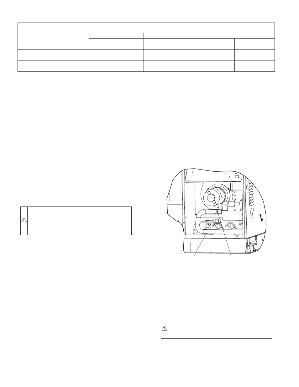
2. Remove pipe plug on manifold (see Fig. 16) then connect
manometer at this point. turn on gas to unit.
3. Record number of seconds for gas meter test dial to make
one revolution.
4. Divide number of seconds in Step 3 into 3600 (number of
seconds on one hour).
5. Multiply result of Step 4 by the number of cu. ft. shown for
one revolution of test dial to obtain cu. ft. of gas flow per
hour.
6. Multiply result of Step 5 by Btu heating value of gas to
obtain total measured input in Btuh. Compare this value
with heating input shown in Table 6. (Consult the local gas
supplier if the heating value of gas is not known.)
EXAMPLE: Assume that the size of test dial is 1 cu. ft., one
revolution takes 32 seconds, and the heating value of the gas is
1050 Btu/ft
3
.
Proceed as follows:
1. 32 seconds to complete one revolution.
2. 3600
÷ 32 = 112.5
3. 112.5 x 1 = 112.5 ft
3
of gas flow/hr.
4. 112.5 x 1050 = 118,125 Btuh input.
If the desired gas input is 115,000 Btuh, only a minor change in the
manifold pressure is required.
Observe manifold pressure and proceed as follows to adjust gas
input:
1. Remove cover screw over regulator adjustment screw on
gas valve.
2. Turn regulator adjustment screw clockwise to increase gas
input, or turn regulator adjustment screw counterclockwise
to decrease input. Manifold pressure must be between 3.4
and 3.6 in. wg.
WARNING: Unsafe operation of the unit may result if
manifold pressure is outside this range. Serious injury or
unit damage may result.
3. Replace cover screw cap on gas valve.
4. Turn off gas supply to unit. Remove manometer from
pressure tap and replace pipe plug on gas valve. Turn on gas
to unit and check for leaks.
TABLE 6—HEATING INPUTS
HEATING
INPUT
(BTUH)*
NUMBER
OF
ORIFICES
GAS SUPPLY PRESSURE
(IN. WG)
MANIFOLD PRESSURE
(IN. WG)
Natural
Propane†
Min
Max
Min
Max
Natural
Propane†
40,000
2
4.0
13.0
7.0
13.0
3.5
3.5
60,000
2
4.0
13.0
7.0
13.0
3.5
3.5
90,000
3
4.0
13.0
7.0
13.0
3.5
3.5
115,000
3
4.0
13.0
7.0
13.0
3.5
3.5
130,000
3
4.0
13.0
7.0
13.0
3.5
3.5
*When a unit is converted to propane, different size orifices must be used. See separate natural-to-propane conversion kit instructions.
†Based on altitudes from sea level to 2000 ft. above sea level. For altitudes above 2000 ft., reduce input rating 4% for each 1000 ft. above sea level. In Canada, from 2000
ft. above sea level to 4500 ft. above sea level, derate the unit 10%.
Fig. 16—Burner Assembly
C99019
MANIFOLD
PIPE PLUG
—14—