Fast & Fluid Giotto Column User Manual
Page 13
Fast & Fluid Management
A Unit of IDEX Corporation
________________________________________________________________________________
________________________________________________________________________________
12
1154915C-it,en,fr.doc - 15/10/2003
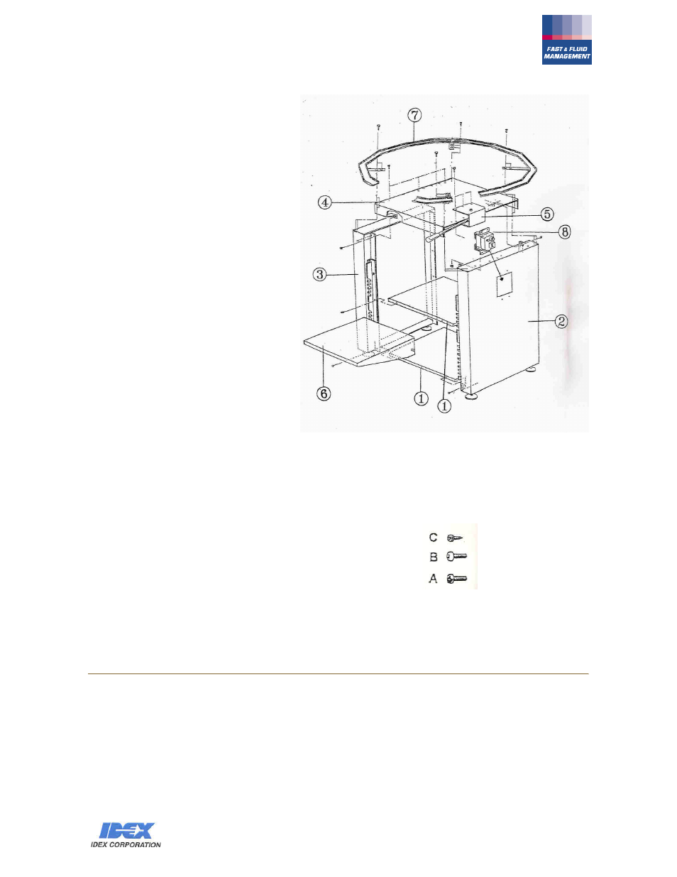
3.- ASSEMBLY
1)
Identify the right side (2) and the left
one (3).
Put the base shelf (1) in the correct
position with the fixing holes on the
front and back
sides. (DIAGRAM 2
).
Fix it with the screws "type C"
(DIAGRAM 2).
2)
Insert the intermediate shelf (1).
Fix it on the holes of the side panels (2)
and (3) using screws"type B", and
nut.(DIAGRAM 1).
3)
Insert from the top the support plane
(4).
Fix it on the front and back sides using
screws "type C", to the side panels (2)
and (3).
4)
After having fixed the support plane (4)
on the side panels (2) and (3), fix with
self threading screws "type C", the
drip tray (7) using n. 2 holes on the
squares.
5)
Fix the complete support brake (5) with
screws "type A"
6)
Put the control box (8), connected to
the motor, in its rectangular housing,
positioned on the right side (2), using
self threading screws "type C"
(DIAGRAM 2)
7)
Pass the power plug , through one of
the two fairleads , placed on the back
panel and make sure that it is
connected to a socket with a good earth
contact.
DIAGRAM 2
NOTE:
"C" code 1193850 self threading T.C. cross-slotted screw 3.9x9.5
"B" code 1184802 screw T.C.E.I. M6x16 UNI 5931
"A" code 1193804 T.C. cross-slotted screw M6x16 DIN 7985
Lower the turning table (10) onto the motor shaft pre-assembled on the support plane (4) and block
it using washer and screw (DIAGRAM 3).
Assemble on the turning table (10) complete canisters (9), inserting them in their place . Block each
canister on the turning table (10), from below, using the screws supplied and keeping free hole (15).
(DETAIL 2) - (DIAGRAM 3)
4.- ASSEMBLY OF THE CAN SUPPORT SHELF
Insert the bar (12) in the can support shelf and mount the shelf at the appropriate lever of the rack
according to the size of the can to be dosed (DIAGRAM 3) - (DETAIL 3)