Bull bar fitment to vehicle – ARB 3421520 User Manual
Page 19
Last Rev Date: 14/10/2010
Page 19 of 22
Fitting instructions# 3787836
Copyright © 2005 by ARB Corporation Limited. All rights reserved, this document must not be reproduced without the express authority of ARB Corporation Ltd
BULL BAR FITMENT TO VEHICLE
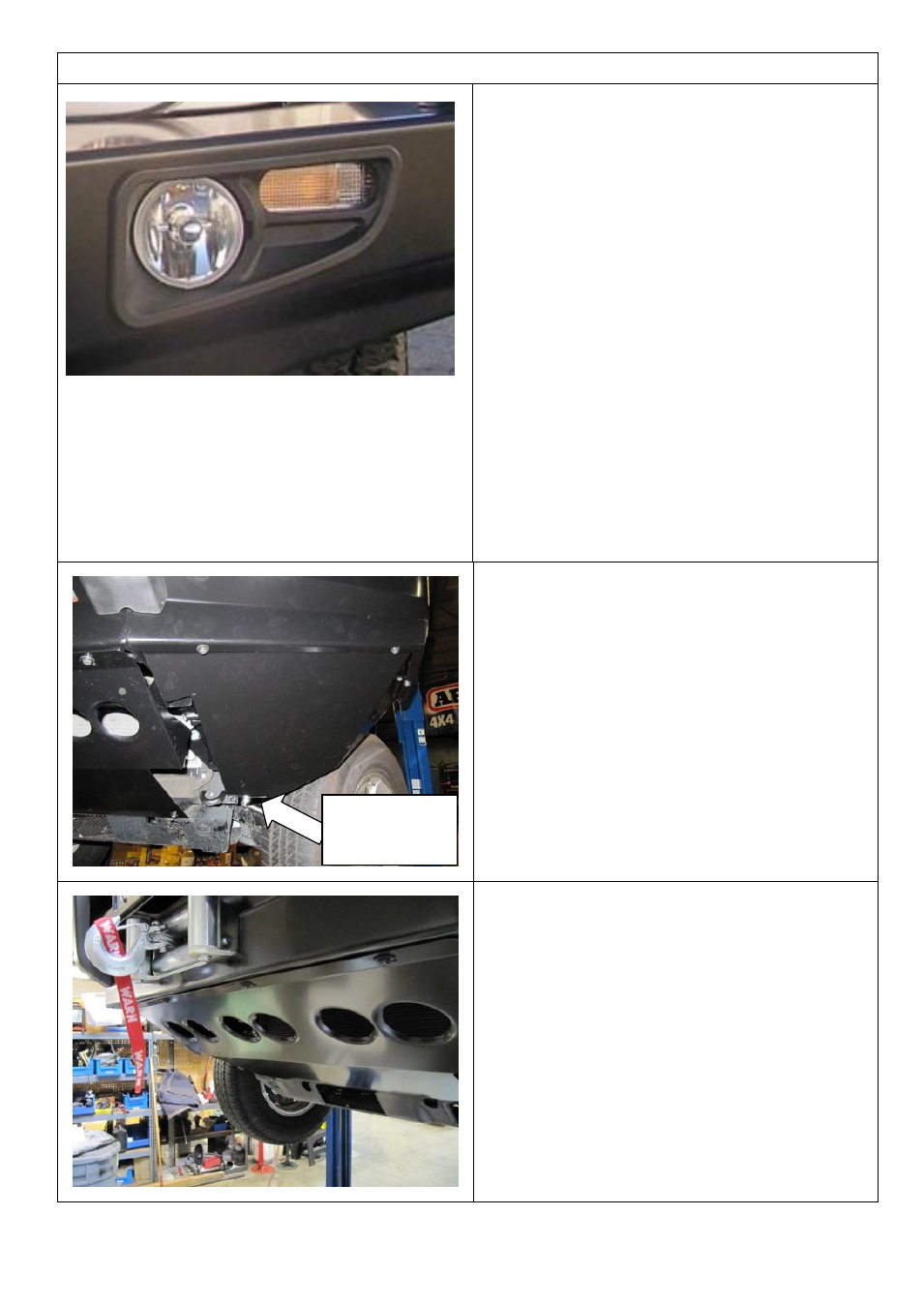
78. Assemble and install combination light
surrounds (p/n 3163015) as per instructions
no. 3786421 supplied with surround kit. Note:
Optional fog lamps can be installed at this
point as per fitting instruction no. 3783315
supplied with fog lamp kit no. 6821201.
79. Check that the lights clear the bumper cut
line, if not trim the bumper edge to clear by at
least 15mm
80. Wire both the positive sides of the indicator
and running lamps together to the vehicles
indicator lamp wiring, black to earth (- neg).
Caution: Cable tie all cables together and
keep all cables clear of sharp edges and
moving parts.
Wiring:
Green wire is Turn signal + (pos)
Red is running lamp + (pos)
Black is ± (neg)
81. Check that all connections have been
made, fog lights, indicators
82. The wing under panels can now be fitted.
83. Fit M6 cage nuts to the inside of the wings
lower flanges, 3 places per wing, also to the
lower inside of the pan.
84. Fit the wing panels as shown and secure
with M6 bolt and washer sets and M8 bolt
and washer set to position on side brace to
chassis
85. The stone shield can now be fitted using 6 x
M6 bolt and washer sets
86. Rear fixing position is to sump guard 2 x M6
captive nuts
M8 bolt and
panel washer
here only