beautypg.com
31
M
ASTER
I
NTAKE
V
ALVE
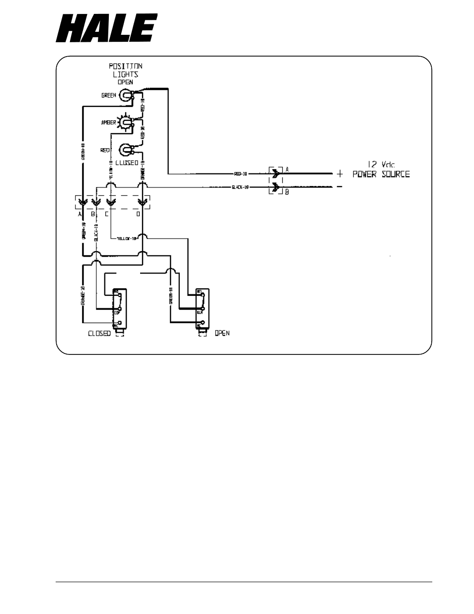
Figure 12. Manual Valve Wiring Diagram
NOTE: Limit switches are shown with the actuatingplungers depressed and the valve in a partially openposition. The amber indicator is lighted with theswitches in this position.
BROWN-18