Aster, Ntake, Alve – Hale Master Intake Valve User Manual
Page 25
23
M
ASTER
I
NTAKE
V
ALVE
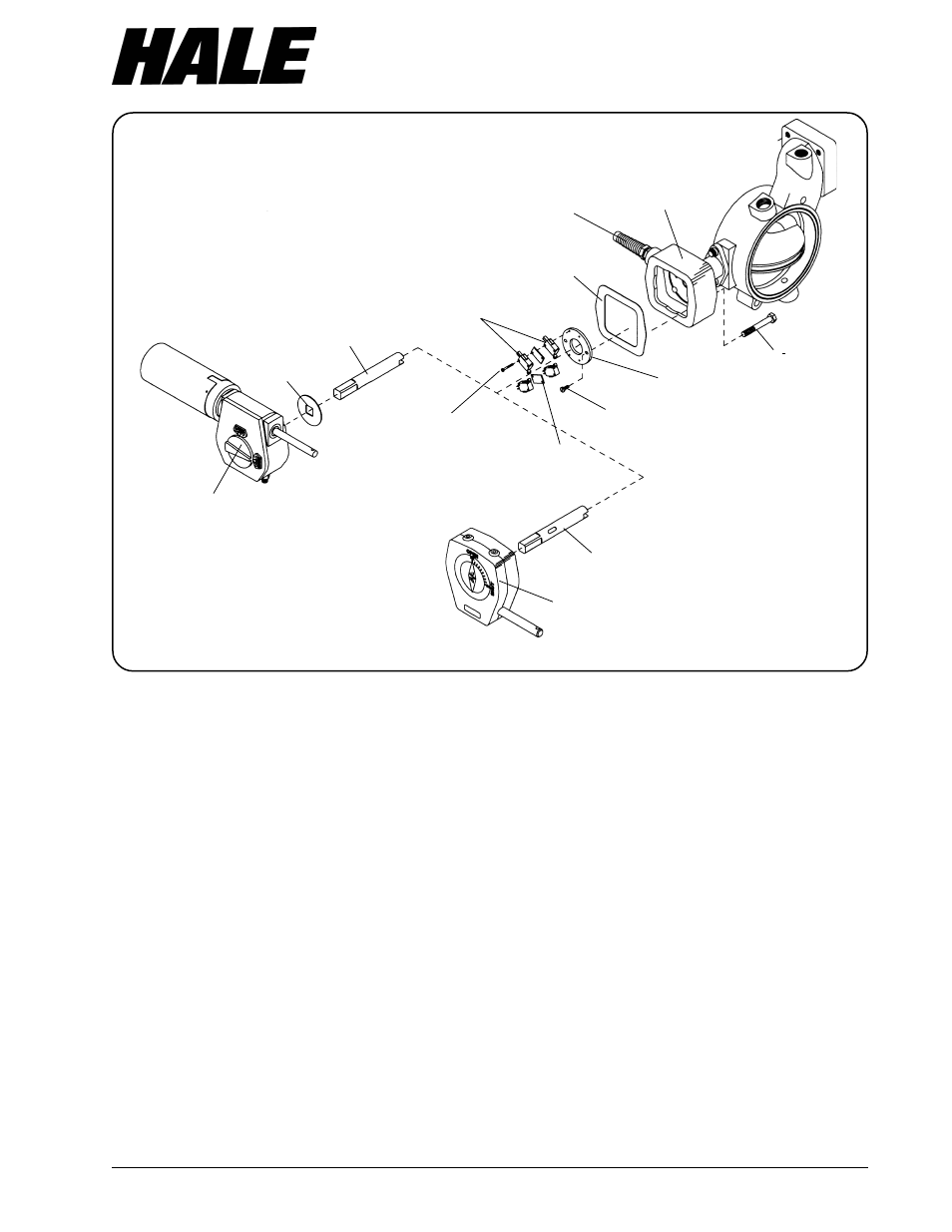
Figure 9. Micro Switch Replacement
MIV-M
GEARBOX
MIV-E GEARMOTOR/
GEARBOX ASSEMBLY
THRUST
WASHER
SHAFT
WIRING
HARNESS
SWITCH
PLATE
#10-24 X ½
SCREW
3
/
8
-16 X 2-½
CAP SCREW
SPACER
(MIV-E)
(MIV-E) #4-40 X 1 SCREW
(MIV-M) #4-40 X ½ SCREW
MICRO SWITCH
(4 REQUIRED MIV-E)
(2 REQUIRED MIV-M)
GEARBOX
ADAPTER
GASKET
SHAFT
tap in the gearbox adapter. Tighten
fitting in ¾ inch NPT tap. Do not tighten
strain relief nut. Push wires through strain
relief, enough to easily attach wires to
switches. Refer to wiring diagrams figure
12 for MIV-M manual valves or figure 13
for MIV-E electric valves. On electric
valves the switches mounted closest
(lower) to switch plate operate motor,
while the upper switches operate the
lights.
15. Carefully pull back on wiring harness
and at the same time insert switch plate
assembly into gearbox adapter.
16. Center switch plate assembly over the
shaft bore. On newer models there is a
raised pilot that switch plate centers on.
Rotate switch plate to align mounting
holes. Apply a coat of Loctite #242 or
equal to threads of two #10-24 x ½ inch
long hex washer head screws. Torque
screws to 22 lb-in (2.5 N-m).
17. Tighten strain relief nut.
18. Install a new gasket to gearbox adapter.
19. Rotate the valve disc to its half open
position. Apply a light coat of Sunoco
Ultra Prestige 2EP grease or equal to the
valve shaft. Insert the shaft into the
gearbox adapter making sure that the
slot in the end of the shaft lines up with
the tang on the end of the valve disc
stem and that the switch sequencing
slot is midway between both sets of
switch rollers. On MIV-E type valves
install the thrust washer over the square
end of the shaft. Lightly grease the top
surface of the thrust washer.