Aster, Ntake, Alve – Hale Master Intake Valve User Manual
Page 13
11
M
ASTER
I
NTAKE
V
ALVE
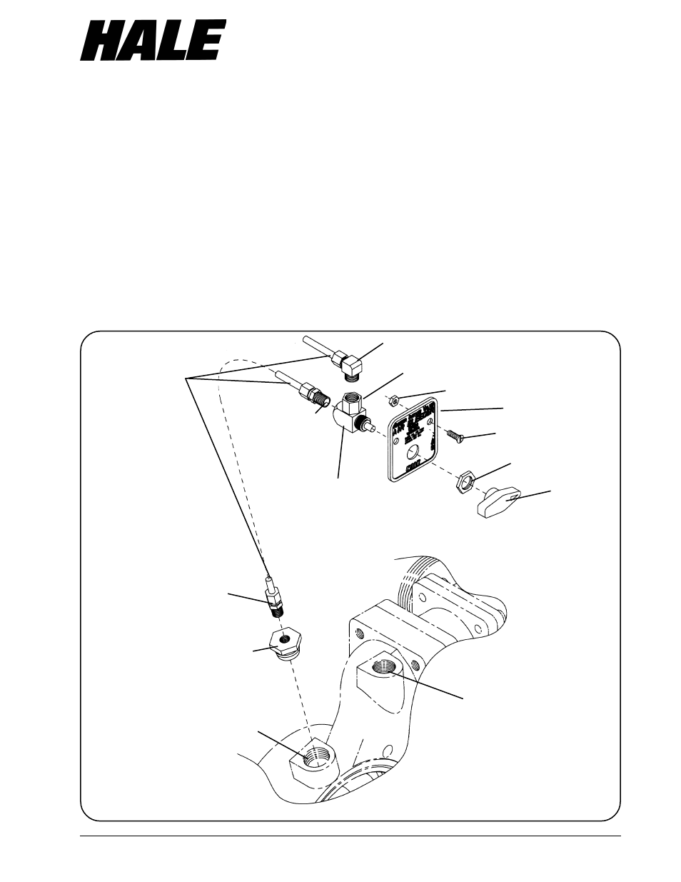
Figure 6. Hale Air Bleeder Valve (ABV) Installation
NPT threaded hole in the bushing.
4. Install the remaining ¼ inch NPT X
3
/
8
inch
tube compression fitting into inlet of the
air bleeder valve body. Hold the valve
with a wrench.
CAUTION: To prevent damage to the
valve body hold the hex outlet on the
valve with a wrench while tightening
elbow.
5.
Install the ¼ inch NPT X
3
/
8
inch tube
compression elbow into the hex outlet of
the air bleeder valve. To prevent
damage to the valve body hold the hex
outlet on the valve with a wrench while
tightening elbow. Make sure the outlet
of the elbow is facing away from the
valve handle.
6. Using a
3
/
32
inch Allen wrench, loosen the
setscrew and remove the valve handle
from the valve body.
7. Remove the retaining nut from the valve
body.
8. Insert the valve body into the panel
placard making sure the elbow is
oriented towards the top of the placard.
3/8 INCH O.D. TUBING
(PROVIDED BY INSTALLER
¼ INCH NPT x 3/8 INCH
TUBE COMPRESSION
FITTING
¼ INCH NPT x 3/8 INCH TUBE
COMPRESSION ELBOW
AIR BLEEDER
VALVE BODY
¾ INCH NPT x ¼ INCH NPT
BUSHING
¾ INCH NPT AIR
BLEED TAPPED HOLE
ON VALVE BODY
¼-20 UNC x 1 INCH LONG
SCREW
¼-20 UNC NUT
DISCHARGES TO
ATMOSPHERE
¾ INCH NPT
OUTBOARD
PRIMING TAP
PANEL
PLACARD
VALVE
HANDLE
AIR BLEEDER VALVE
RETAINING NUT
¼ INCH NPT x 3/8 INCH
TUBE COMPRESSION
FITTING
HOLD THIS HEX WHEN
TIGHTENING ELBOW