Aster, Ntake, Alve – Hale Master Intake Valve User Manual
Page 27
25
M
ASTER
I
NTAKE
V
ALVE
directions. Check lamp operation and
disc stop position, if necessary back out
screw a small amount until lamp and
stop sequence properly.
b) Replace rubber plug.
b. Electric valves (MIV-E)
a) Operate the valve open then
closed. See that motor stops, the red
lamp is lit and valve disc is in the closed
position.
b) Tighten the mechanical stop until
it just touches the segment gear, then
back out ½ to ¾ turn. Lock in place.
c) Operate the valve open then
closed. See that the motor stops
electrically and not against the
mechanical stop. When the motor stops
operating, the handwheel should be
able to rotate about ¾ turn before
stopping against mechanical stop. If
not back out setscrew another ¼ turn
and repeat step.
32. Now operate the disc to the open
position. The mechanical stop can be
set.
a. Manual valves (MIV-M)
a) Tighten the screw until it stops. Do
not over tighten. Operate valve in both
directions. Check lamp operation and
disc stop position, if necessary back out
screw a small amount until lamp and
stop sequence properly.
b) Replace rubber plug.
b. Electric valves (MIV-E)
a) Operate the valve to the open
position. See that motor stops, the
green lamp is lit and valve disc is in the
open position.
b) Tighten the mechanical stop until
it just touches the segment gear, then
back out ½ to ¾ turn. Lock in place.
c) Operate the valve closed then
open. See that the motor stops
electrically and not against the
mechanical stop. When the motor stops
operating, the handwheel should be
able to rotate about ¾ turn before
stopping against mechanical stop. If
not back out setscrew another ¼ turn
and repeat step.
33. Close the operator panel and install the
handwheel.
WARNING: Keep hands and arms clear
of the valve disc when valve is being
operated without suction tube strainer or
suction tube in place.
34. Cycle the valve to ensure smooth
operation.
RELIEF VALVE COMPONENT
REPLACEMENT:
If operation of the relief valve indicates that
component replacement is necessary do
the following:
1. Remove apparatus from service.
2. Remove valve handwheel and
interferences to open pump
compartment cover and gain access to
relief valve.
WARNING: Male threads on relief valve
outlet are sharp and can cause severe
cuts. Be careful when working around
the exposed threads on the relief valve
outlet
3. Disconnect discharge piping from the
relief valve outlet.
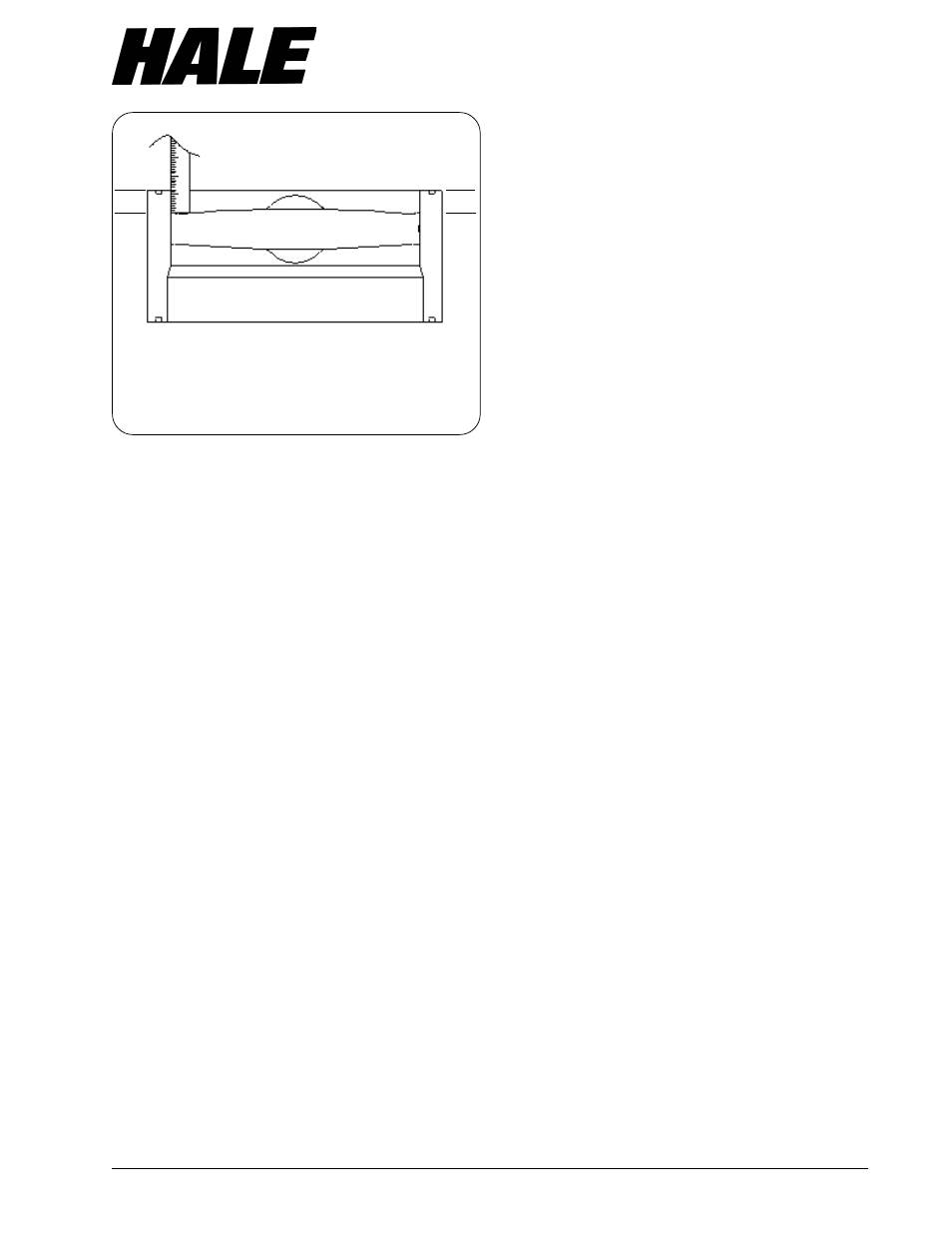
Figure11. Valve Disc Position
Measurement
EXAMPLE:
A MEASURES
5
/
8
INCH
B MUST MEASURE
9
/
16
TO
11
/
16
INCH
DISCHARGE SIDE OF VALVE
A
B
➩
➩
➩
➩
➩
➪
➩
➩
➩
➩
➩
➪
B=A
±±±±±
1
/
16