Brocade Communications Systems Brocade EZSwitchSetup 5100 User Manual
Page 34
22
EZSwitchSetup Administrator’s Guide
53-1002157-01
Connecting devices and completing the setup
2
The Configure Ports and Connect Devices screen provides visual feedback as you cable
the switch. A green line indicates that the connection is correct, a red line indicates an
invalid connection, and a blue line indicates a missing connection.
.
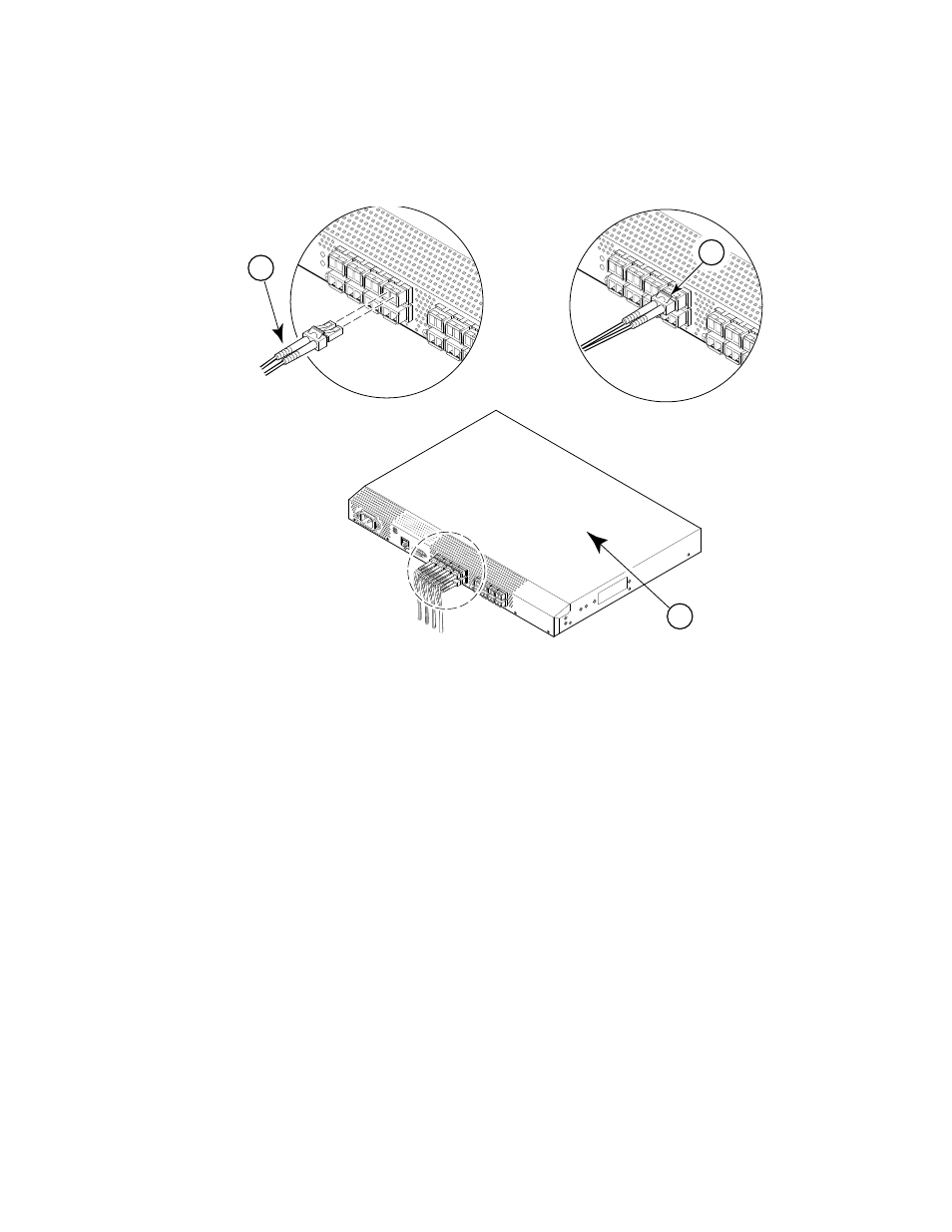
FIGURE 18
Installing Fibre Channel Cable to an SFP
3. Verify that the connections displayed on the Configure Ports and Connect Devices screen are
all green.
4. Click Next.
The Finish screen is displayed.
1
Position the Fibre Channel cable
3
Brocade switch
2
Install the Fibre Channel cable
scale: 1/8" = 1"
!
IOIO
I
ATT
ENT
ION:
Max
imu
m s
crew
len
gth
for
rac
k
mo
unt
ing
to b
e 5
mm
or
13/
64
in.
2
1
3