Appendix d – system piping (continued) – Burnham ES2 User Manual
Page 38
38
(2)
Comply with the boiler’s specific
water quality requirements. See the
Specifications Section of this manual.
(3)
Comply with the boiler’s specific
requirements for minimum water flow
through the boiler, installing a system
bypass or primary-secondary loop if
necessary to maintain flow through the
boiler when serving small zones.
3.
Overpressure
(1)
Install a properly sized expansion tank.
(2)
Do not exceed the boiler’s specific
requirements for maximum allowable
working pressure.
(3)
Do not plug or block the relief valve.
4.
Freezing
(1)
Run all portions of the system piping
inside a heated space unless the system
is properly protected with an inhibited
antifreeze solution.
5.
Overheating
(1)
Comply with the boiler’s specific
requirement for minimum water flow
through the boiler. See the
Specifications Section of this manual.
(2)
Install a low-water cutoff device
whenever the boiler is installed above
the level of the lowest heat emitter
or radiator. Also add a low-water
cutoff when required by local code
requirements.
6.
Thermal shock
(1)
Do not over-pump. Adhere to the design
flow requirements for each zone.
(2)
Install a boiler bypass, system bypass,
or primary-secondary loop when needed
to avoid returning large volumes of cold
water directly to a hot boiler.
7.
Condensation
(1)
Do not over-pump. Adhere to the design
flow requirements for each zone.
(2)
Adhere to the boiler’s specific
minimum return water and supply water
temperature requirements. Install a
boiler bypass, system bypass, or
primary-secondary loop when needed to
maintain water temperatures and flows
within the specified limits.
(3) Do not allow chilled water to enter the
boiler during the heating cycle, or heated
water to enter chilled water coils during
the cooling cycle.
8.
Dry Fire
Install a low-water cutoff when the boiler
is installed above the level of the lowest
radiator and when required by local code.
i
The following system diagrams are intended to provide a minimum level of guidance for a
successful and trouble-free installation of the boiler in common applications. They do not substitute
for proper design, evaluation, and installation by a trained and qualified installer using the proper
tools, techniques, and design expertise. Not all options are available with every boiler.
APPeNDIX D – System Piping (continued)
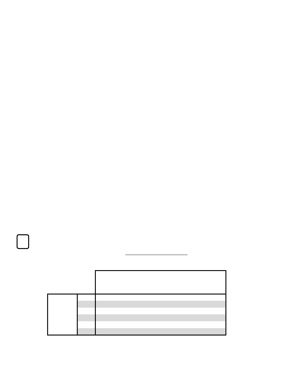
Hot Water Boilers, Non-Condensing
Indirect Tank?
Two or more
zones of
the same
temperature?
Two or more
zones of
different
temperatures?
Two or
more
boilers?
See
Diagram
D-W1
D-W2
D-W3 Tankless Coil
D-W4
D-W5
D-W6