Physical installation, Front panel leds, Physical installation front panel leds – ADTRAN 3010 NTU-8 User Manual
Page 10: Figure 2, Ntu-8f rear panel, Table 2
Total Access 3000/3010 NTU-8 Single Fiber Quad E1 Installation and Maintenance Practice
4
61182301E1-5A
Physical Installation
To install the NTU-8F, perform the following steps:
1. Place the unit in a location where a DC power source is available. This unit operates
within a voltage range of –24 VDC to –48 VDC. If a wall-mount installation is required,
attach the supplied hangers to the unit.
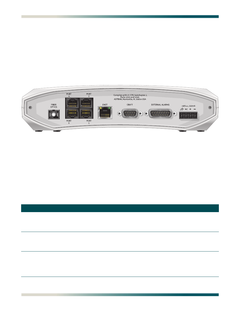
2. Connect power to the NTU-8F housing. Power is connected to the NTU-8F by connecting
the plus (+), minus (–), and ground wires to a three-position terminal block located at the
right of the backplane (see
).
Figure 2. NTU-8F Rear Panel
When the NTU-8F first powers up, it runs power up self-tests. Once the power up self-test is
complete, the status LEDs will reflect the true state of the hardware.
Front Panel LEDs
The NTU-8F provides front panel LEDs to display status information. The NTU-8F LEDs and
status descriptions are shown in
Table 2. Front Panel LEDs
Label
Status
Description
PWR
{
z
z
Off
Green
Yellow
Power supply or fuse failure
In Service
Out of Service-Unassigned or Maintenance
OPT
{
z
z
Off
Green
Red
Unit is Out of Service-Unassigned
Unit is active and optical interface is synchronized
Unit is active, but Rx loss on the optical interface
PORT 1-4
{
z
z
z
Off
Green
Yellow
Red
Port is provisioned Out of Service-Unassigned
Port is provisioned and functioning properly
Port is in loopback or a BERT is active
Port is active with an active major alarm condition