10 line impedance selection, 11 coder/motorola/intel selection, 12 g.772 monitoring address selection – Cirrus Logic CDB61884 User Manual
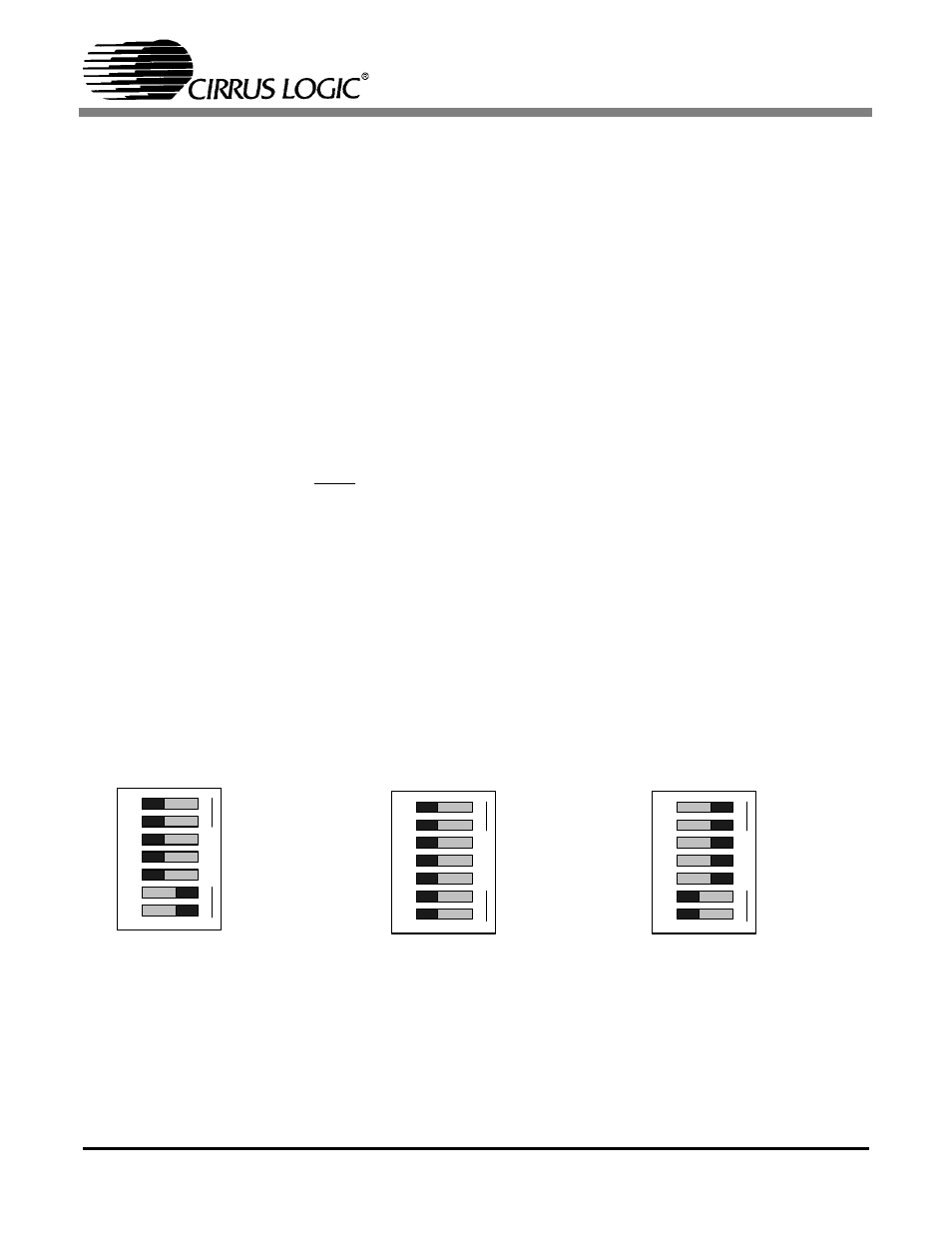
Page 8: 13 mux/non-mux/bits clock selection, Figure 9. switch s9 settings
CDB61884
8
DS485DB1
In host mode, switches S12 through S14 (LEN2-0)
must be set to the open (middle) position to allow
host processor control.
2.10
Line Impedance Selection
In hardware mode, switch S11 (CBLSEL), in com-
bination with the LEN 2-0 switches are used to set
the internal or external line impedance for all eight
channels. Refer to the CS61884 Data Sheet for the
CBLSEL settings.
In host mode, switch S11 has no effect on the
CS61884 device and should be set to the NC (mid-
dle) position.
2.11
Coder/Motorola/Intel Selection
In hardware mode, switch 1 (MOT/INTL) inside
switch block S9 (S9 #1) is used to enable AMI or
HDB3/B8ZS line coding. Setting switch S9 #1 to
the open (HIGH) position enables AMI coding and
the closed (low) position enables HDB3/B8ZS cod-
ing.
In host mode, switch S9 #1 is used to select either
Motorola or Intel parallel host mode. When set to
the open (HIGH) position Intel mode is selected
and the closed (LOW) position enables Motorola
mode.
shows the settings for switch S9 #1
in hardware and parallel host mode.
2.12
G.772 Monitoring Address Selection
In hardware mode, the address for the G.772 Non-
Intrusive monitoring feature is selected by switches
3 through 7 (A4-A0) inside switch block S9. When
switches 3 through 7 inside switch block S9 are all
set to the closed “LOW” position, the G.772 Non-
Intrusive monitoring function is disabled. Refer to
the CS61884 Data Sheet for more address settings.
In host mode, switches 3 through 7 inside switch
block S9 must be set to the open (high) position so
that the host interface can have control over the ad-
dress signals during parallel host modes.
2.13
Mux/Non-Mux/BITS Clock Selection
In hardware mode, switch 2 (MUX) inside switch
block S9 enables or disables the Channel #0 G.703
BITS Clock function. Placing switch S9 #2 in the
open “HIGH” position enables Channel #0 G.703
BITS Clock function and the closed “LOW” posi-
tion disables this function.
In host mode, switch S9 #2 (MUX) is used to select
multiplex or non-multiplex. Placing switch S9 #2
Hardware Mode - Enables
AMI coding & enables
Channel 0 G.703 Bits
Clock function
Hardware Mode - Enables
HDB3/B8ZS coding &
disables Channel 0 G.703 Bits
Clock function
Parallel Host Mode -
Enables Motorola Non-
Multiplex parallel host mode
LO
S9
O
PEN
HI
MOT_\INTL
MUX
A0
A1
A2
A3
A4
1
234
56
7
LO
S9
O
PEN
HI
MOT_\INTL
MUX
A0
A1
A2
A3
A4
1
2
345
67
LO
S9
O
PEN
HI
MOT_\INTL
MUX
A0
A1
A2
A3
A4
1
2
345
67
Figure 9. Switch S9 Settings