3 t1/j1 100 w mode setup, 3 t1/j1 100, Table 6. t1/j1 100 – Cirrus Logic CDB61884 User Manual
Page 20
CDB61884
20
DS485DB1
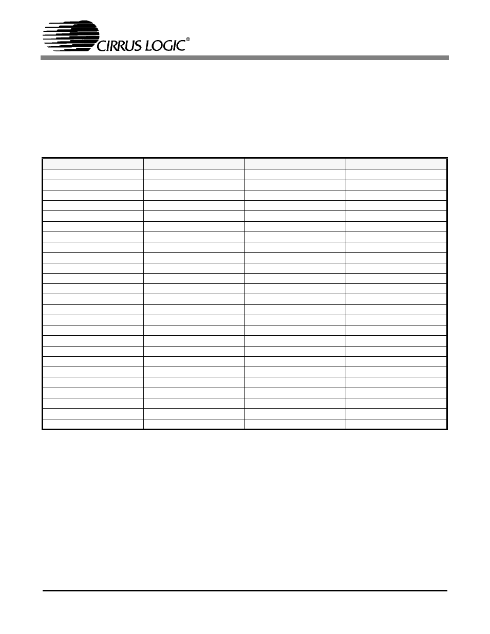
6.3 T1/J1 100
Ω
Mode Setup
shows the position of the different switches and jumpers used to set up the CDB61884 evaluation
board to operate in T1/J1 100
Ω
Hardware, Serial Host and Parallel Host operational modes. Before se-
lecting host mode the switches in
in bold should be set to the position stated.
8. Set “LOW” to disable receiver Internal line impedance matching function. The external resistors for all
eight receivers must be changed to 12.5
Ω
to properly match the input line impedance.
9. Selects T1/J1 100
Ω
0ft-133ft line length settings. These pins can be changed to select other T1/J1 100
Ω
line length settings. Refer to the CS61884 Data Sheet for other settings.
Table 6. T1/J1 100
Ω
Operational Mode Switch/Jumper Position
Switches/Jumpers
Hardware
Serial Host (Note 3)
Parallel Host (Note 3)
S15 (MODE)
HARDWARE
SERIAL HOST
PARALLEL HOST
S1 (0)
LOOP FUNCTION
NONE
NONE
S2 (1)
LOOP FUNCTION
NONE
NONE
S3 (2)
LOOP FUNCTION
NONE
NONE
S4 (3)
LOOP FUNCTION
NONE
NONE
S5 (4)
LOOP FUNCTION
NONE
NONE
S6 (5)
LOOP FUNCTION
NONE
NONE
S7 (6)
LOOP FUNCTION
NONE
NONE
S8 (7)
LOOP FUNCTION
NONE
NONE
S9 #1 (MOT_\INTL)
OPEN (HIGH)
HIGH
MOTOROLA/INTEL
S9 #2 (MUX)
LOW (Note 4)
HIGH
MUX/NON-MUX
S9 #3 (A4)
LOW (Note 5)
HIGH
HIGH
S9 #4 (A3)
LOW (Note 5)
HIGH
HIGH
S9 #5 (A2)
LOW (Note 5)
HIGH
HIGH
S9 #6 (A1)
LOW (Note 5)
HIGH
HIGH
S9 #7 (A0)
LOW (Note 5)
HIGH
HIGH
S10 (JASEL)
ANY POSITION
OPEN
OPEN
S11 (CBLSEL)
NC or HIGH (Note 8)
NC
NC
S12 (LEN 2)
LOW (Note 9)
OPEN
OPEN
S13 (LEN 1)
HIGH (Note 9)
OPEN
OPEN
S14 (LEN 0)
HIGH (Note 9)
OPEN
OPEN
J13 (VLOGIC)
3V
3V
3V
J1 (MCLK)
OSCILLATOR
OSCILLATOR
OSCILLATOR
J93 (CLKE)
OPEN
OPEN
OPEN
J23 (TXOE)
OPEN
OPEN
OPEN