2 mask registers, Table 6. mask registers, Ds261pp5 – Cirrus Logic CS61584A User Manual
Page 25
CS61584A
DS261PP5
25
DS261PP5
Latched-AIS: Set high on the rising edge of the
alarm indication signal condition. Reading the Sta-
tus register clears the Latched-AIS bit and deacti-
vates the INT pin. Refer to the timing diagram in
Figure 18.
Latched-BPV: Indicates a bipolar violation has
been received since the last read of the Status reg-
ister. Reading the Status register clears the
Latched-BPV bit and deactivates the INT pin. This
bit is set only when the line code decoder is enabled
in the Control A register.
Latched-Overflow: Indicates a waveform generat-
ed using the Arbitrary Waveform register has ex-
ceeded full scale since the last read of the Status
register. Reading the Status register clears the
Latched-Overflow bit and deactivates the INT pin.
Latched-Reset: Indicates a reset event (power-up or
RESET pin) has occurred since the last read of the
Status register. Reading the Status register clears
the Latched-Reset bit and deactivates the INT pin.
This bit is not maskable.
Latched-CLKLOST: Set high when TCLK or REF-
CLK are absent. Reading the Status register clears
the Latched-CLKLOST bit and deactivates the INT
pin.
Interrupt: Indicates a change in the Status register
since the last read. Reading the Status register
clears the Interrupt bit and deactivates the INT pin.
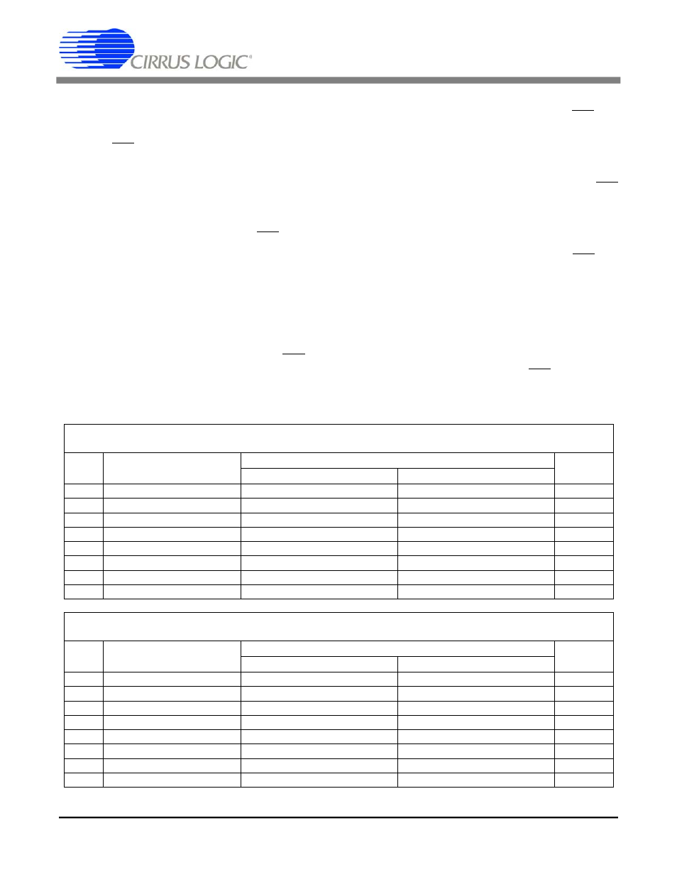
9.1.2
Mask Registers
The Mask registers are read-write registers and are
shown in Table 6. The Mask registers disables the
interrupts in the corresponding Status register on a
per-bit basis. Masking a Status register bit forces it
to remain at zero and prevents the INT pin from ac-
tivating on the condition.
Mask Register (Channel 1)
Serial Port Address: 0x12; Parallel Port Address: 0xY2
Bit
Description
Definition
Reset
Value
1
0
7
Mask LOS1
Mask Interrupt
Enable Interrupt
0
6
Mask Latched-LOS1
Mask Interrupt
Enable Interrupt
0
5
Mask AIS1
Mask Interrupt
Enable Interrupt
0
4
Mask Latched-AIS1
Mask Interrupt
Enable Interrupt
0
3
Mask Latched-BPV1
Mask Interrupt
Enable Interrupt
0
2
Mask Latched-Overflow1
Mask Interrupt
Enable Interrupt
0
1
Automatic All Ones, AAO
Ones at RPOS/NEG on LOS
Zeros at RPOS/NEG on LOS
0
0
Mask Interrupt1
Mask Interrupt
Enable Interrupt
0
Mask Register (Channel 2)
Serial Port Address: 0x13; Parallel Port Address: 0xY3
Bit
Description
Definition
Reset
Value
1
0
7
Mask LOS2
Mask Interrupt
Enable Interrupt
0
6
Mask Latched-LOS2
Mask Interrupt
Enable Interrupt
0
5
Mask AIS2
Mask Interrupt
Enable Interrupt
0
4
Mask Latched-AIS2
Mask Interrupt
Enable Interrupt
0
3
Mask Latched-BPV2
Mask Interrupt
Enable Interrupt
0
2
Mask Latched-Overflow2
Mask Interrupt
Enable Interrupt
0
1
Mask Latched-CLKLOST
Mask Interrupt
Enable Interrupt
0
0
Mask Interrupt2
Mask Interrupt
Enable Interrupt
0
Table 6. Mask Registers
CS61584A
DS261F1
25