Switching characteristics, Cs5560 – Cirrus Logic CS5560 User Manual
Page 6
CS5560
6
DS713PP2
5/4/09
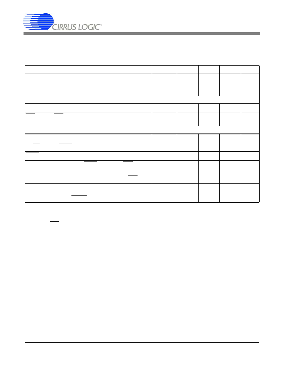
SWITCHING CHARACTERISTICS
T
A
= -40 to +85 °C; V1+ = V2+ = +2.5 V, ±5%; V1- = V2- = -2.5 V, ±5%;
VL - VLR = 3.3 V, ±5%, 2.5 V, ±5%, or 1.8 V, ±5%
Input levels: Logic 0 = 0V = Low; Logic 1 = VD+ = High; CL = 15 pF.
7.
BP/UP can be changed coincident CONV falling. BP/UP must remain stable until RDY falls.
8.
If CONV is held low continuously, conversions occur every 320 MCLK cycles.
If RDY is tied to CONV, conversions will occur every 322 MCLKs.
If CONV is operated asynchronously to MCLK, a conversion may take up to 324 MCLKs.
RDY falls at the end of conversion.
9.
RDY will fall when the device is fully operational when coming out of sleep mode.
Parameter
Symbol Min Typ
Max
Unit
Master Clock Frequency
Internal Oscillator
External Clock
XIN
f
clk
12
0.5
14
16
16
16.2
MHz
MHz
Master Clock Duty Cycle
40
-
60
%
Reset
RST Low Time
t
res
1
-
-
µs
RST rising to RDY falling
Internal Oscillator
External Clock
t
wup
-
-
120
1536
-
-
µs
MCLKs
Conversion
CONV Pulse Width
t
cpw
4
-
-
MCLKs
BP/UP setup to CONV falling
t
scn
0
-
-
ns
CONV low to start of conversion
t
scn
-
-
2
MCLKs
Perform Single Conversion (CONV high before RDY falling)
t
bus
20
-
-
MCLKs
Conversion Time
Start of Conversion to RDY falling
t
buh
-
-
324
MCLKs
Sleep Mode
SLEEP low to low-power state
SLEEP high to device active (Note 9)
t
con
t
con
-
-
50
3083
-
-
µs
MCLKs