7 ain & vref sampling structures, 8 converter performance, Figure 8. cs5560 dnl plot – Cirrus Logic CS5560 User Manual
Page 19: Cs5560
CS5560
DS713PP2
19
5/4/09
3.7 AIN & VREF Sampling Structures
The CS5560 uses on-chip buffers on the AIN+, AIN-, and the VREF+ inputs. Buffers provide much higher
input impedance and therefore reduce the amount of drive current required from an external source. This
helps minimize errors.
The Buffer Enable (BUFEN) pin determines if the on-chip buffers are used or not. If the BUFEN pin is
connected to the V1+ supply, the buffers will be enabled. If the BUFEN pin is connected to the V1- pin,
the buffers are off. The converter will consume about 30 mW less power when the buffers are off, but the
input impedances of AIN+, AIN- and VREF+ will be significantly less than with the buffers enabled.
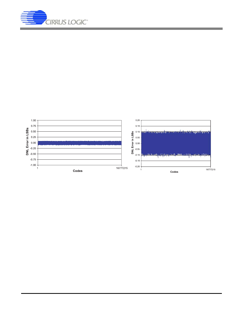
3.8 Converter Performance
The CS5560 achieves excellent differential nonlinearity (DNL) as shown in Figure 8. Figure 8 illustrates
the code widths on the typical scale of ±1 LSB and on a zoomed scale of ±0.2 LSB.
Figure 8. CS5560 DNL Plot
(Zoom View)