13 synchronizing multiple converters, Figure 23. more complex multiplexing scheme, Figure 23 – Cirrus Logic CS5560 User Manual
Page 27: Cs5560
CS5560
DS713PP2
27
5/4/09
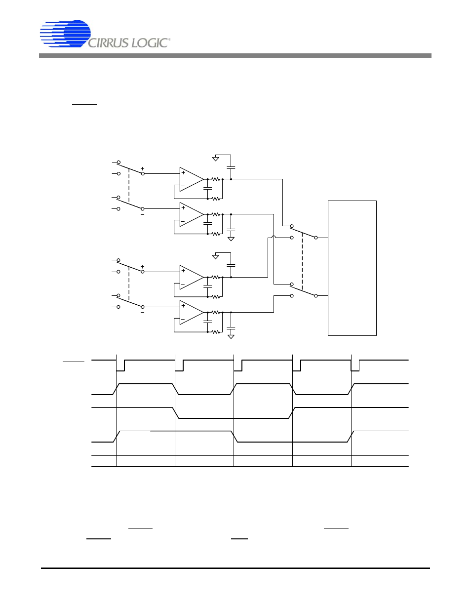
At the same time the converter is performing a conversion on a channel from one bank of multiplexers,
the second multiplexer bank is used to select the channel for the next conversion. This configuration al-
lows the buffer amplifier for the second multiplexer bank to fully settle while a conversion is being per-
formed on the channel from the first multiplexer bank. The multiplexer on the output of the buffer amplifier
and the CONV signal can be changed at the same time in this configuration. This multiplexing architec-
ture allows for maximum multiplexing throughput from the A/D converter. The following figure depicts the
recommended analog input amplifier circuit.
Figure 23. More Complex Multiplexing Scheme
3.13 Synchronizing Multiple Converters
Many measurement systems have multiple converters that need to operate synchronously. The convert-
ers should all be driven from the same master clock. In this configuration, the converters will convert syn-
chronously if the same CONV signal is used to drive all the converters, and CONV falls on a falling edge
of MCLK. If CONV is held low continuously, reset (RST) can be used to synchronize multiple converters
if RST is released on a falling edge of MCLK.
CS556x
AIN+
AIN-
49.9
47pF
4.99k
4700pF
C0G
49.9
47pF
4.99k
4700pF
C0G
49.9
47pF
4.99k
4700pF
C0G
49.9
47pF
4.99k
4700pF
C0G
B1+
B2+
B1-
B2-
CH1
CH2
C1+
C2+
C1-
C2-
CH3
CH4
SW2
SW3
SW1
A1+
A2+
A1-
A2-
CONV
Convert on CH1
Convert on CH1
Convert on CH4
Convert on CH2
Convert on CH3
Select A1
Select A2
Select A1
Select A2
Select B1
Select B2
Select B1
Select A1
Select C1
Select C2
Select C1
SW1
SW2
SW3