2 digital section, Cdb5550 – Cirrus Logic CS5550 User Manual
Page 5
CDB5550
5
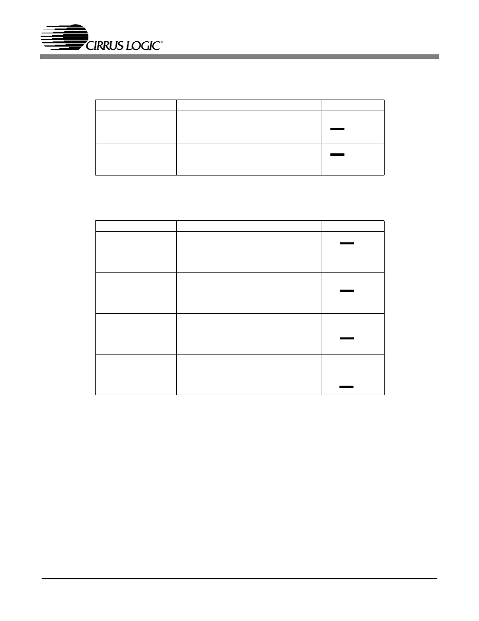
The CDB5550 also provides options for sourcing the voltage reference for the CS5550. These options
include the on-chip reference (VREFOUT), or an external reference. The voltage reference selection is
controlled via the header J7. Refer to Table 2.
Table 2. VREFIN Source Selection
A selectable voltage divider for the external reference is also provided. The external voltage applied to the
terminal block J4 can be divided by a factor of 1, 2, 4, or 8. The voltage divider is controlled by header J1.
Refer to Table 3.
Table 3. External Voltage Divider Selection
1.2.2 Digital Section
The digital section of the CDB5550 consists of the microcontroller, interface header, reset circuitry, and
the USB interface. The microcontroller handles the communication between the PC and the CS5550. This
device is pre-programmed and requires no additional code in order to operate.
An SPI interface header is provided via J8 for use with an external microcontroller. However, if an external
microcontroller is used, the on-board microcontroller (U3) must be disconnected from the SPI port. This
can be accomplished by removing the 0 ohm resistors R11, R12, R13, R15, R17, and R18.
The CDB5550 has a pushbutton reset switch, S1. This reset button will reset the microcontroller which
will then reset the CS5550, resetting all registers to their default values.
Reference
Description
J7
Ext VREF
Selects the external voltage reference
(J4)
CS5550 VREFOUT
Selects the internal voltage reference
from the CS5550
Reference
Description
J7
/1
Divides the external voltage applied to J4
by a factor of 1
/2
Divides the external voltage applied to J4
by a factor of 2
/4
Divides the external voltage applied to J4
by a factor of 4
/8
Divides the external voltage applied to J4
by a factor of 8
O O VREFOUT
O O Ext VREF
O O VREFOUT
O O Ext VREF
O O /1
O O /2
O O /4
O O /8
O O /1
O O /2
O O /4
O O /8
O O /1
O O /2
O O /4
O O /8
O O /1
O O /2
O O /4
O O /8